26 JVL Industri Elektronik A/S - User Manual - Integrated Stepper Motors MIS23x, 34x, 43x
2.6 RS485 Interface
2.6.1 RS485 - General description when using a QuickStep motor
The RS485 interface offers
more noise immune commu
-
nication compared to a USB
or RS232 interface
. Up to 32
motors can be connected to
the same interface bus.
When connecting the RS485
interface to a central control
-
ler, the following rules must
be followed:
1 Use twisted pair cable.
2 Use shielded cable.
3 Make sure that the GND is
also connected.
4 Ensure that all units have a
proper connection to safety
ground (earth) in order to
refer to the same potential.
5 The last unit in each end of
the network must be termi
-
nated with a 120 Ohm re-
sistor between A and B.
6 Ensure that the supply lines
are made individually in or
-
der to reduce the voltage
drop between the motors.
7Central Controller RS485
interface:
If available, it is strongly rec-
ommended a type with op-
tical isolation is used.
The default configuration:
Databits = 8
Baud rate = 19200
Stop bit = 1
Parity = None
Central
Controller
(for example a PC)
QuickStep motor or
SMC75 Controller
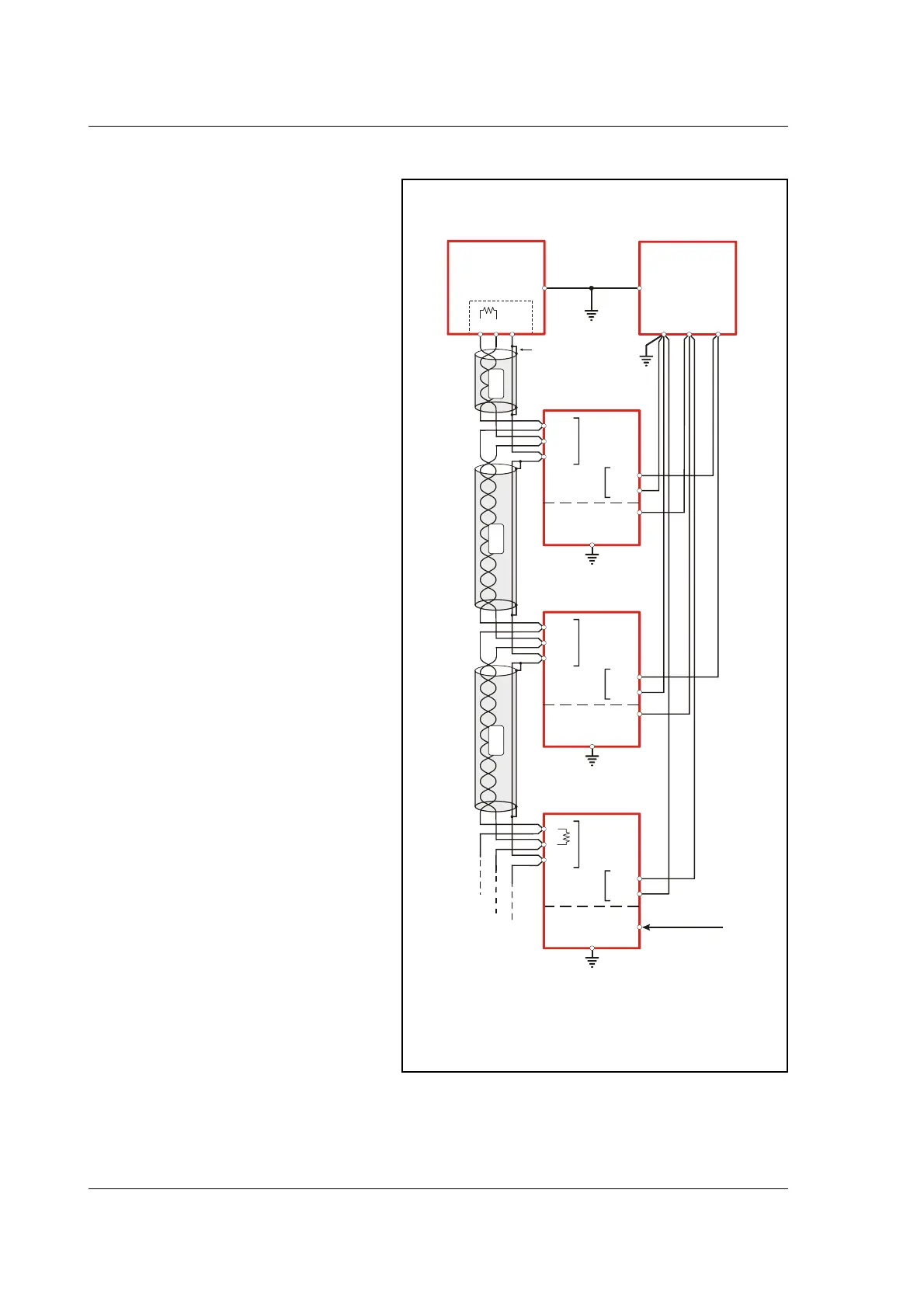
RS485 network with 1 x QuickStep, 1 x MAC140 and 1 x MAC80
mounted with MAC00-B1, B2 or B4 modules.
MAC50-141
Motor
MAC800
Motor
Power supply
A
A
A
A
P+
P+
P+
B
B
B
B
P-
P-
P-
RS485
Interface
Screen connected
to GND in each end
Opto isolation *
**
**
** The last unit in each end of the line must be terminated. The MAC00-B1, B2
and B4 contain this feature. See the individual module descriptions.
The QuickStep motor does not have a resistor built-in, the resistor
has to be mounted externally, for instance in the M12 connector.
Make sure that all
involved units are
connected to the same
potential
RS485
Interface
RS485
Interface
Up to 32
Motors
TT2181GB
Power
Supply
Power
Supply
Power
Supply
Mains 230VAC
Control voltage
CVI
Control voltage
Only MAC50-141 with
B2 or B4 (Optional)
GND
GND
+12-32VDC
(control voltage)
+12-48VDC
(Bus voltage)
GND
GND
GND
O+
Main supply
ScreenScreen Screen
Max. 32VDC !
* Opto isolation is recommended.
*** Each unit connected must be setup with an address via The MacTalk program.
If only one unit is connected no address is needed.
*** Address=1
*** Address=2
*** Address=3

 Loading...