106 JVL Industri Elektronik A/S - User Manual - Integrated Stepper Motors MIS23x, 34x, 43x
6.4 Gear Mode
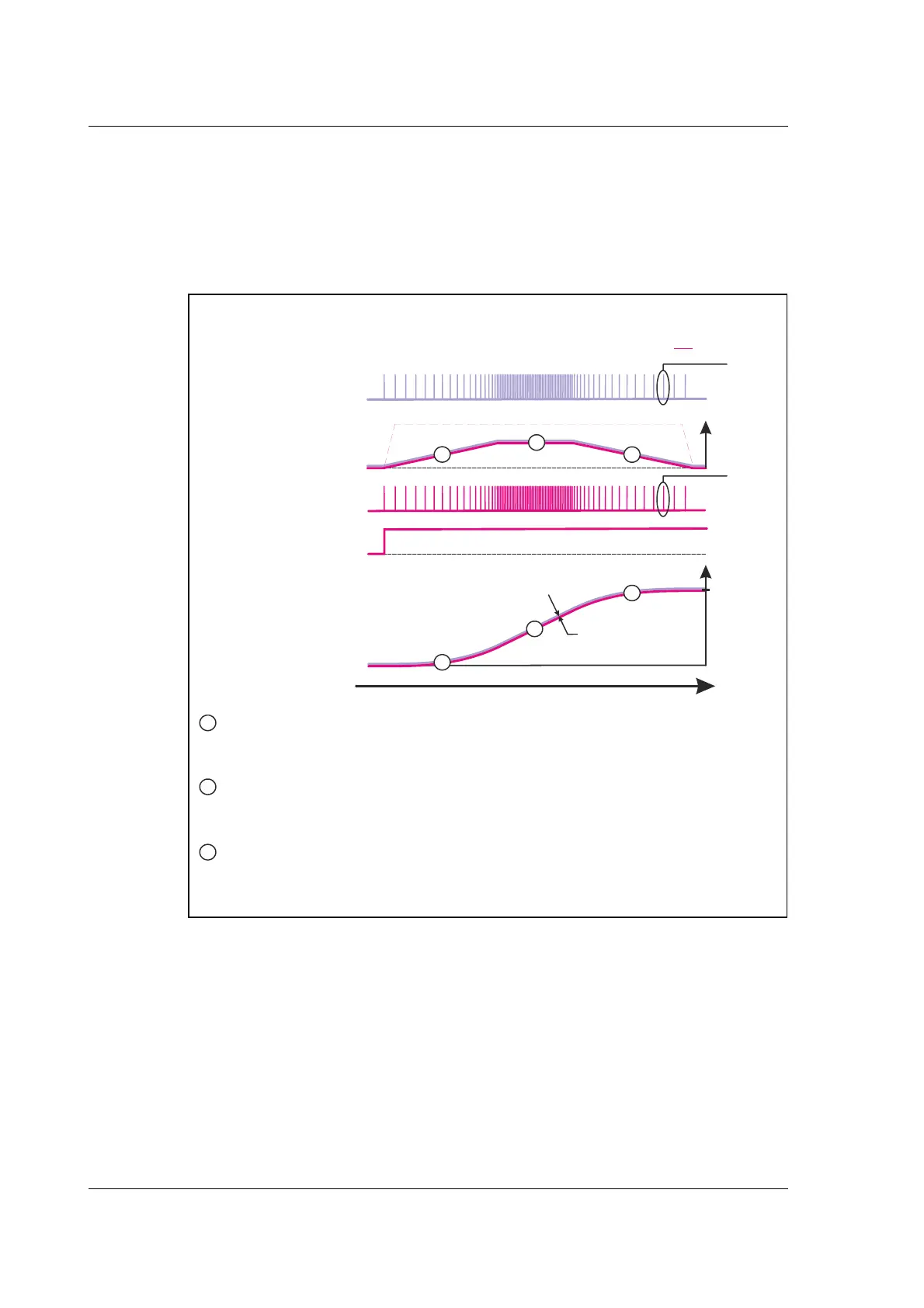
As an alternative to the previous illustration the full control can be done by the master
by setting the velocity and acceleration registers to a significant higher value than the
equivalent value of the clock source which will assure that the motor follows each clock
with a very narrow timing and no delays.
This solution must be used if the master that produces the clocks do generate the full
motion profile with acceleration to a desired top speed and make sure to decelerate and
hit target.
TT24
-
1
B
Motor steps(counts)
In total 80 steps moved
Motor Direction
Motor Velocity
(Slave)
Input position
(Master)
Motor position
(Slave)
Input clock
In total 80 steps received
Time
Positio
Target
1 step
Minimum
position error
The master that produce the input clock to the motor takes care of producing
acceleration. Since the acceleration register in the motor is set to a high value
it will not limit the demanded acceleration.
0
0
CW
CCW
elocity
e
at
on
etween
nput an
t
e motor
e
av
our w
en sett
ng t
e
velocity and acceleration registers to values.
Motion speed and acceleration/deceleration only and .
high
controlled by the master the motornot
1
1
1
2
2
2
3
3
Similar as during acceleration the velocity register have been set to a high
value and do not cause any limitation of what is demanded from the master
producing the input clocks.
Same relation as during acceleration. The motor will reach target (80 counts)
exactly without any overshoot or time delay compared to the master position.
3
Input Velocity
(Master)
1 step
Acc. and vel. envelope = much larger than source

 Loading...