262334 69 Revision A
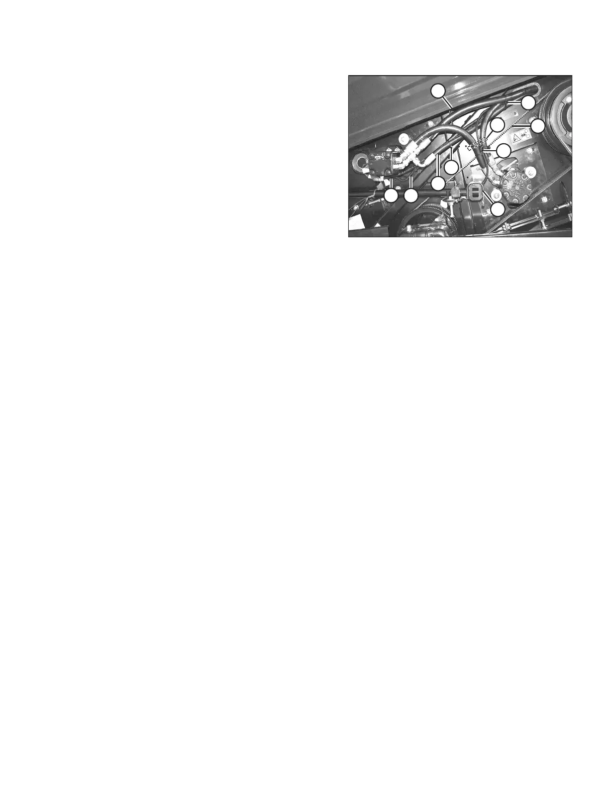
Figure 3.92: Adjusted Configuration – M100, M105,
and M205
9. Secure the hose routing with cable ties (A) as shown.
IMPORTANT:
Ensure that electrical harness (B) and reel motor case drain
hose (C) are secured to hose (D) and that there is at least
25 mm (1 in.) clearance between hose bundle (E) and knife
drive timing belt (F).
IMPORTANT:
Ensure there is enough clearance between the hoses and
any hardware that may need to be accessed to adjust the
reel or auger.
10. Orient the fittings and, if necessary, use a cable tie to
ensure a minimum clearance of 20 mm (3/4 in.) between
hoses and bolt at location (G).
11. Orient the fittings to provide a minimum of 10 mm (3/8 in.)
clearance between the hoses and unplug the tool at
location (H).
12. Orient the fittings to provide a minimum of 200 mm
(7 7/8 in.) clearance between the end panel and the hoses
in location (J).
OPERATION