ASSEMBLING THE W INDROWER
19. Connect header drive hoses (A) and electrical
harness (B) to header. Refer to the draper header
operator’s manual.
Figure 3.199: Header Drive Hoses and Harness
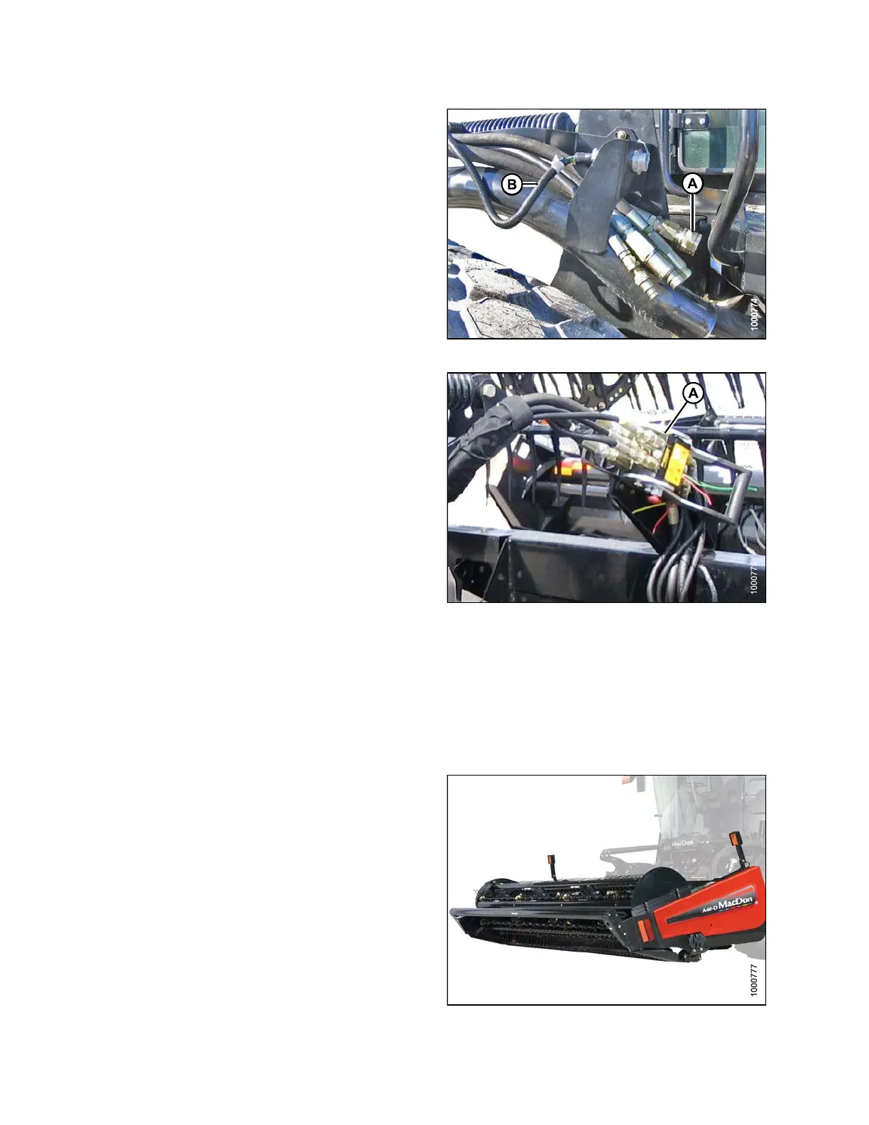
20. Connect reel hydraulics (A) at right cab-forward
side of windrower. Refer to the draper header
operator’s manual.
21. Start engine and raise and lower the header and the
reel a few times to remov e trapped air.
Figure 3.200: Reel Hydraulics
3.21.3 Attaching an A-Series Header
A30-D
, A30-S, and A40-D headers can be attached to an M105, M155, or M205 Self-Propelled Windrower. For
attac
hment procedure, refer to the section for your specific windrower model.
M105 S
elf-Propelled Windrower
The M105 Self-Propelled Windrower is factory-equipped to
run an A-Series Auger Header.
Windrowers equipped with A-Series hydraulics have four
header drive hoses on the left cab-forward side.
The attachment procedure varies depending on the type
of center-link installed on the windrower. Refer to the
following instructions based on th e type o f link installed o n
your windrower:
• Attaching an A-Series Header: H ydraulic Center-Link
without Self-Alignment, page 121
• Attaching an A-Series Header: Mechanical Center-Link,
page 127
Figure 3.201: M105 and A40-D Auger H eader
147962
11
4
Revision A