CAB DISPLAY MODULE (CDM)
3. Press right (C) arrow to select YES. Press
SELECT (D).
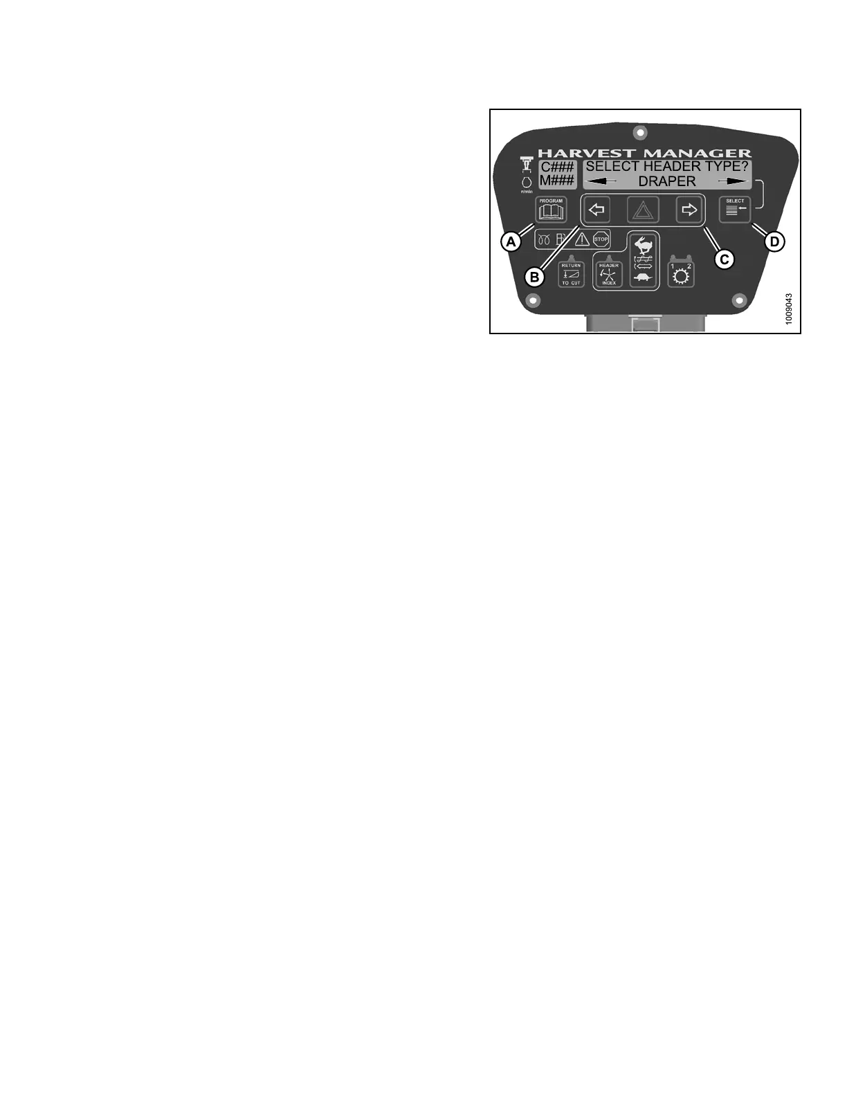
• SELECT HEADER TYPE? is displayed on the
upper line.
• Previouslyinstalled header flashes on thelower line.
NOTE:
The default header type is DRAPER.
4. Press left (
B) or right (C) arrow to cycle header type on
lower lin e.
Select head
er type from the following:
• DRAPER
•A30AUGER
•A40AUGER
NOTE:
Knife drive pump may require adjustment after
changing header type.
Figure 4.7
3: Header Ty pe
5. Press SELECT.
6. Press PROGRAM to
exit Programming Mode or
press SELECT to p
roceed to next WINDROWER
SETUP action.
4.4.2 Activating the Hydraulic Center-Link on an M105 and M155
NOTE:
• This procedure requ
ires installation of the optional Hydraulic Center-Link (MD #B 4 65 0) and option al Aux iliary
Valve (MD #B5269).
• Displaying center-
link position on cab display module (CDM) requires installation of the optional Expansion
Module (MD #B4666 ).
For more information, refer to the windrower operator’s manual or the windrower
technical manual.
147962 185 Revision A