ASSEMBLING THE W INDROWER
Attaching an A-Series Header: Hydraulic Center-Link with Optional Self-Alignment
DANGER
To avoid bodily injury or death from unexpected startup of the machine, always stop the engine and remove
the key from the ignition before leaving the operator ’s seat for any reason.
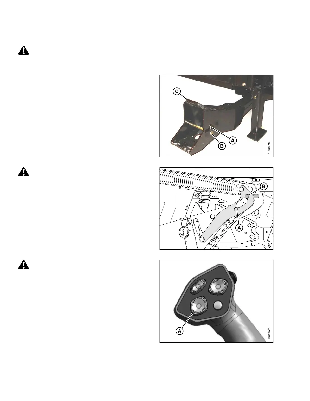
1. Remo ve hairpin (A) from clevis pin (B) and remove
clevis pin from the header boots (C) on both sides of
the header.
Figure 3.204: Header Boot
CAUTION
To prevent damage to the lift system when lowering
header lift linkages without a header or weight
box attached to the windrower, ensure the float
engagement pin is installed in storage position (B)
and NOT in engaged position (A).
Figure 3.205: Header Float Linkage
CAUTION
Check to be sure a ll bystanders have cleared t he area.
2. Start t
he engine and act iva te the HEADER DOWN
button
(A) on the ground speed lever (GSL) to fully
retrac
t header lift cylinders.
Figure 3.206: Ground Speed Lever
147962 116 Revision A