ASSEMBLING THE W INDROWER
3.4 Installing Drive Wheels
NOTE:
If using the factory stand , proceed to Step 1, page 34; otherwise, skip to Step 5, page 34.
1. Ensure the thr
ee (one at rear, two at front) lift locks are
activated on
the lift mechanism.
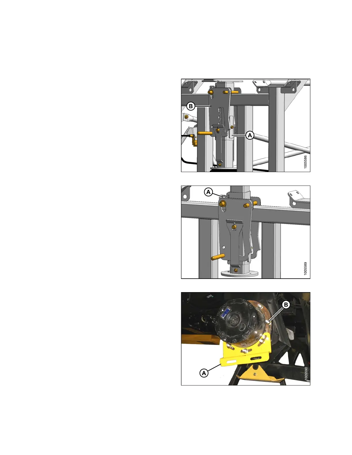
NOTE:
Lock is ac tiva ted wh en keep er (A) is v ertical and
latch (B) is free to move back and forth.
2. Pressurize the air bag system (690 kPa [100 psi] air
pressure required) and raise the windrower to the
maximum height (approximately 178 mm [7 in.]) above
the stand.
Figure 3.13: Lift Locks
3. Verify t h
at all three locks are engaged before
proceedi
ng to the next step.
NOTE:
Lock is engaged when the witness hole (A)
above the pin is exposed.
4. Release pressure until the locks support the weight of
the windrower.
Figure 3.14: Lift Locks
5. Remov
e shipping support (A) from the drive wheel hub,
and re
move the wheel lug nuts (B).
Figure 3.15: Drive Wheel Shipping Support
147962 34 Revision A