ASSEMBLING THE WINDROWER
CAUTION
Check to be sure all bystanders have cleared the area.
18. Start the e ng ine a nd activa te the HEADER DOWN
switch (A) on the GSL to fully lower the hea de r.
19. Stop engine and remove key from ignition.
Figure 3.217: Ground Speed Lever
20. Connect h
eader drive hoses (A) and electrical
harness (
B) to header. Refer to the auger header
operator
’s manual.
Figure 3.218: Heade r Drive Hose s and Harnes s
Attaching an A-Series Header: Hydraulic Center-Link without Self-Alignment
DANGER
To avoid bodily injury or death from unexpected startup of the machine, always stop the engine and remove
the key from the ignition before leaving the operator’s seat for any reason.
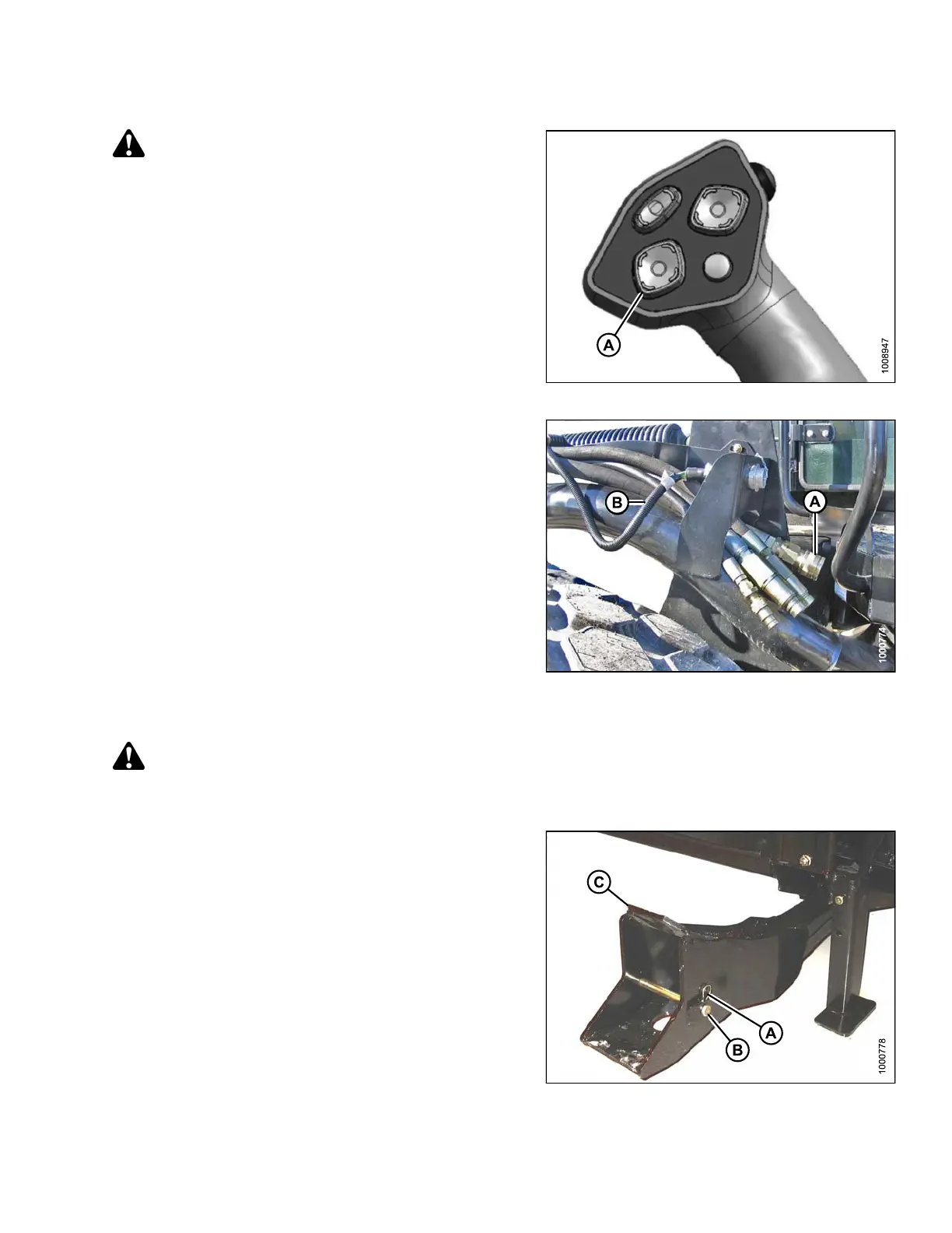
1. Remove hairpin (A) from clevis pin (B) and remove
clevis pin from the header boots (C) on both s ides of
the header.
Figure 3.219: Header Boot
147962
12
1
Revision A