CAB DISPLAY MODULE (CDM)
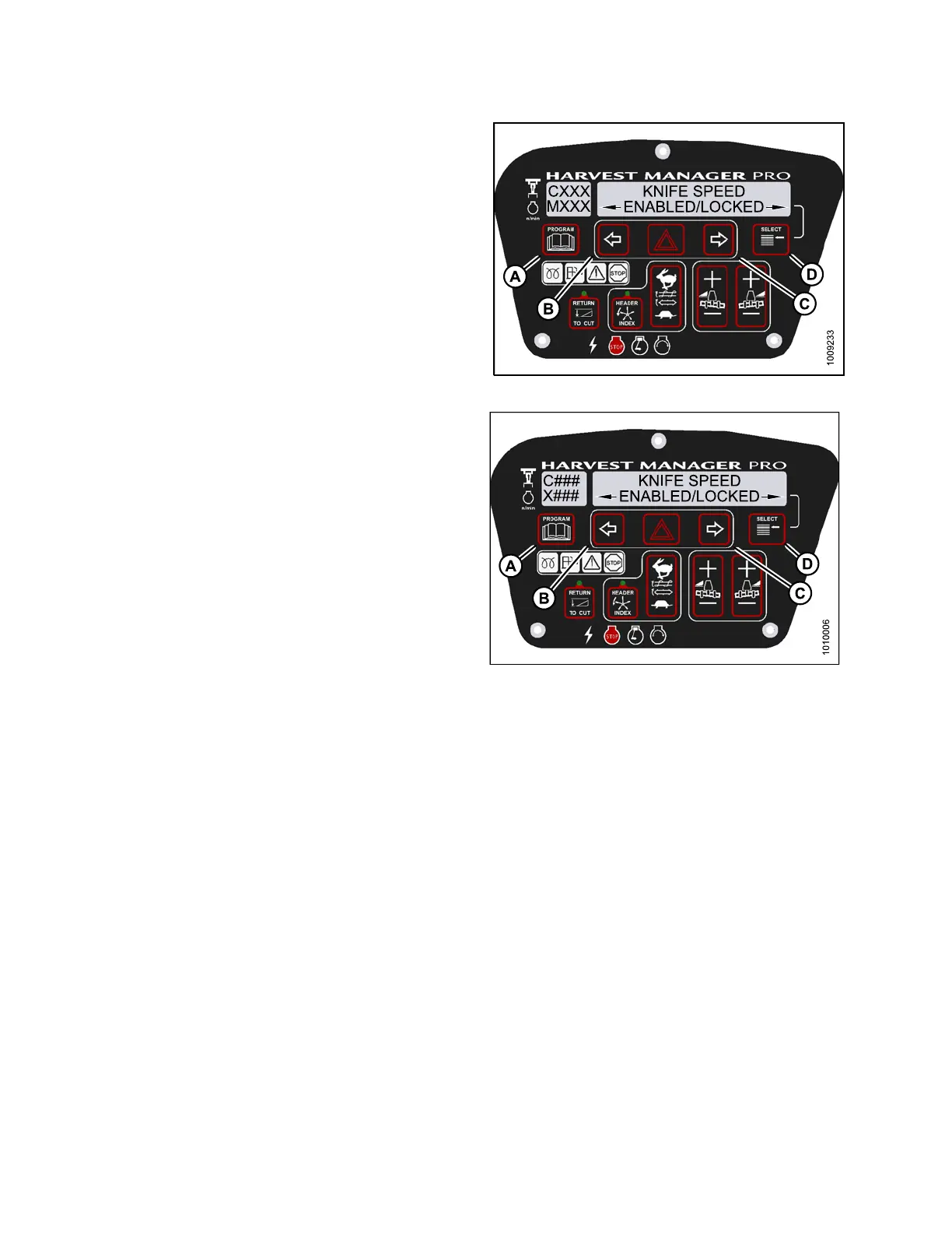
6. Press SELECT (D) until KNIFE SPEED is displayed on
the upper line.
• ENABLED/L O C KED is displayed on the lower line.
7. Press left arrow (B) to enable KNIFE SPEED control
switch, or press right arrow (C) to lock KNIFE SPEED
control switch.
8. Press PROGRAM (A) to exit Programming Mode or
press SELECT (D) to p roceed to next WINDROWER
SETUP action.
Figure 4.1
62: M155 Knife Speed Control Lock
Figure 4.163: M205 Knife Speed Control Lock
4.5.2 Activating Rotary Disc Speed Control Lockout
NOTE
:
•This
procedure is for rotary disc headers only.
•Theh
eader MUST be attached t o the windrower to pe rf orm this procedure. The cab displa y module (CDM)
aut
omatically adjusts its programming for each header.
147962
22
4
Revision A