CAB DISPLAY MODULE (CDM)
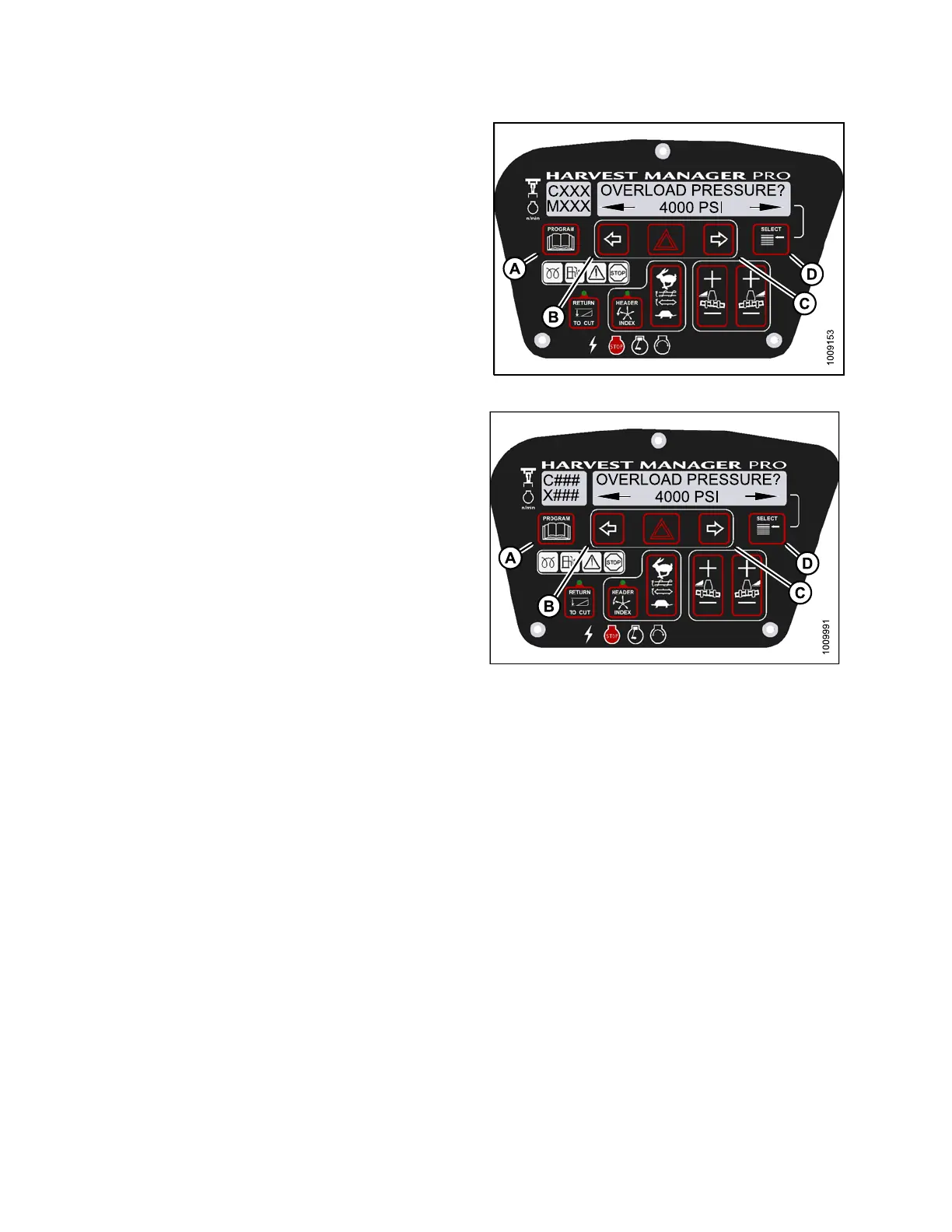
4. Press SELECT (D) until OVERLOAD P RESSU RE? is
displayed on the upper line.
• The curre nt overload pressure is displayed on
lower line .
NOTE:
Pressure ran
ge is 17,237–34,474 kPa
(2500–5000 p
si).
5. Press left (
B) or right (C) arrows to set hydraulic
overload pr
essure. Press SELECT (D).
6. Press PROGR
AM (A) to exit Programming Mode or
press SELEC
T (D) to proceed to next WINDROWER
SETUP acti
on.
Figure 4.9
8: M155 Hydraulic Overload Pressure
Figure 4.99: M205 Hydraulic Overload Pressure
4.4.9 Setting the Header Index M ode
Head
er Index feature is not applicable to rotary headers.
NOTE:
The header MUST be attached to the windrower to perform this procedure. The cab display module (CDM)
automatically adjusts its programming for each header.
NOT
E:
•Fo
r M105 Self-Propelled Windrowers, the header MU ST be attached to the windrower to perform this procedure.
Th
is menu is suppressed if the A30 Header is attached.
•Fo
r M105 Self-Propelled Windrowers, displaying reel speed on cab display module (CDM) requires installations
of
the optional Expansion Module (MD #B4666). For more information, refer to the windrower operator ’s manual
o
r the windrower technical manual.
147962 196 Revision A