ASSEMBLING THE W INDROWER
CAUTION
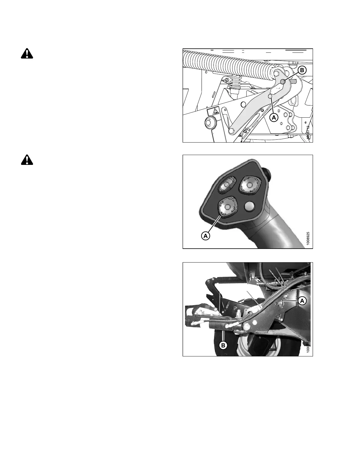
To prevent damage to the lift system when lowering
header lift linkages without a header or weight
box attached to the windrower, ensure the float
engagement pin is installed in storage position (B)
and NOT in engaged position (A).
Figure 3.220: Header Float Linkage
CAUTION
Check to be sure a ll bystanders have cleared t he area.
2. Start the engine and activate the HEADER DOWN
button (A) on the ground speed lever (GSL) to fully
retract header lift cylinders.
Figur
e 3.221: Ground Speed Lever
3. Relocate pin (A) in frame linkage as required to
raise the center-link (B) until the hook is above the
attachment pin on the header.
IMPORTANT:
If the center-link is too low, it may contact the
header as the windrower approaches the header
for hookup.
Fig
ure 3.222: Hydraulic Center-Link without
Se
lf-Alignm ent Kit
147962
12
2
Revision A