ASSEMBLING THE W INDROWER
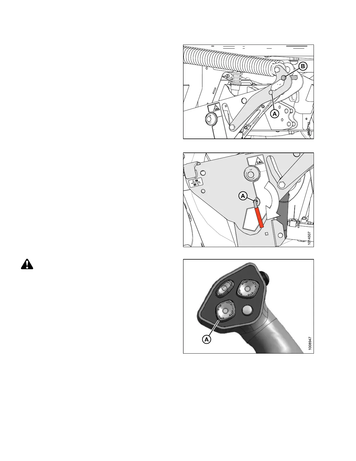
12. Remove cle vis pin from storage po sition (B) in link ag e
and insert into hole (A) to eng age float springs. Sec ure
with hairpin.
Figure 3.287: Header Float Linkage
13. Disengage safety prop by turning lever (A) downwards
to release and lower stop until lever locks into
vertical position.
14. Repeat for opposite safety prop.
Figure 3.288: Safety Prop
CAUTION
Check to be sure a ll bystanders have cleared t he area.
15. Start the eng ine and activate the HEADER DOWN
switch (A) on the GSL to fully lower the header.
16. Stop engine and remove key from ignition.
Figure 3.289: Ground Speed Lever
147962 148 Revision A