MAX32660 User Guide
Maxim Integrated Page 107 of 195
10.4 One-Shot Mode (000b)
In One-shot mode the timer peripheral increments TMRn_CNT until it matches TMRn_CMP and then stops incrementing
and disables the timer. The timer can optionally output a pulse on the timer pin at the end of the timer period. In this
mode, the timer must be re-enabled to start another one-shot mode event.
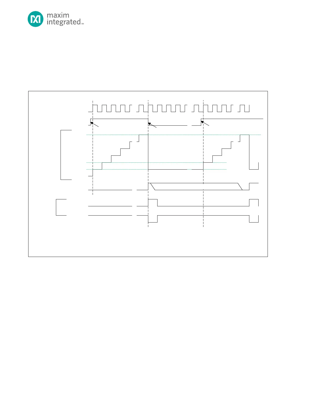
Figure 10-1: One-Shot Mode Diagram
TMR_CN.TEN
TMR_CNT
0X0000_0000**
0X0000_0001*
TMR_INT.IRQ
TIMER CLOCK
TMR_CMP
* TMR_CNT AUTOMATICALLY RELOADS WITH 0X0000_0001 AT THE END OF THE TIMER PERIOD, BUT SOFTWARE CAN WRITE ANY INITIAL VALUE TO TM R_CNT
BEFORE THE TIMER IS ENABLE D.
** THE DEFAULT VALUE OF TM R_CNT FOR THE FIRS T PE RIOD AFTER A SY STEM RESET IS 0X0000_0000 UNLESS CHANGED BY SOFTWARE.
TMR_CN.TPL = 1
TMR_CN.TPL = 0
TIMER PIN
(OUTPUT)
0X0000_0002
TIMER ENABLED
BY SOFTWARE
TIMER DISABLED
BY HARDWARE
TIMER ENABLED
BY SOFTWARE
SOFTW ARE CLEARS BIT
10.4.1 Timer Period
The timer period ends on the timer clock following TMRn_CNT = TMRn_CMP.
The timer peripheral automatically performs the following actions at the end of the timer period:
1. TMRn_CNT is reset to 0x0000 0001.
2. The timer is disabled by setting TMRn_CN.ten = 0.
3. If the timer output is enabled, the timer pin is driven to its active state for one timer clock. It then returns to its
inactive state.
4. The timer interrupt bit TMRn_INT.irq will be set. An interrupt will be generated if enabled.
 Loading...