MAX32660 User Guide
Maxim Integrated Page 109 of 195
10.5 Continuous Mode (001b)
In Continuous mode, the timer peripheral increments TMRn_CNT until it matches TMRn_CMP, resets TMRn_CNT to
0x0000 0001, and continues incrementing. The timer peripheral can optionally toggle the state of the timer pin at the end
of the timer period.
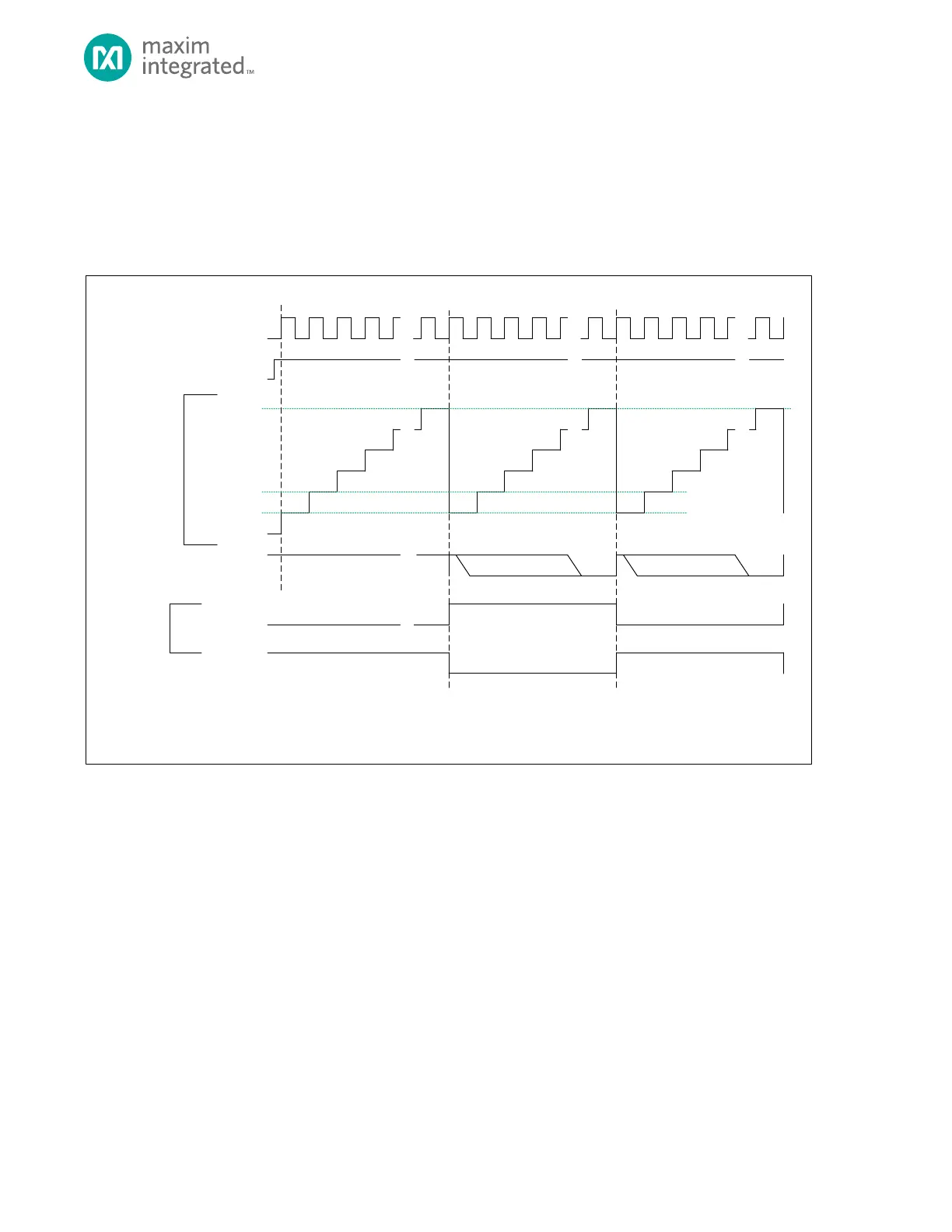
Figure 10-2: Continuous Mode Diagram
TMR_CN.TEN
TMR_CNT
0X0000_0000**
0X0000_0001*
TMR_INT.IRQ
TIMER CLOCK
TMR_CMP
* TMR_CNT AUTOMATICALLY RELOADS WITH 0X0000_0001 AT THE END OF THE TIMER PERIOD, BUT SOFTW ARE CAN WRITE ANY INITIAL VALUE TO TMR_CNT
BEFORE THE TIMER IS ENABLE D.
** THE DEFAULT VALUE OF TM R_CNT FOR THE FIRST PERIOD AFTER A SYSTEM RE SET IS 0X0000_0000 UNLESS CHA NGED BY SOFTWARE .
SOFTWARE CLEARS BIT
TMR_CN.TPL = 1
TMR_CN.TPL = 0
TIMER PIN
(OUTPUT)
0X0000_0002
SOFTW ARE CLEARS BIT
10.5.1 Timer Period
The timer period ends on the timer clock following TMRn_CNT = TMRn_CMP.
The timer peripheral automatically performs the following actions at the end of the timer period:
1. TMRn_CNT is reset to 0x0000 0001. The timer remains enabled and continues incrementing.
2. If the timer output is enabled, the timer pin toggles state (low to high or high to low).
3. The timer interrupt bit TMRn_INT.irq will be set. An interrupt will be generated if enabled.