MAX32660 User Guide
Maxim Integrated Page 119 of 195
10.10 Gated Mode (110b)
Gated mode is like continuous mode, except that TMRn_CNT only increments when the timer pin is in its active state.
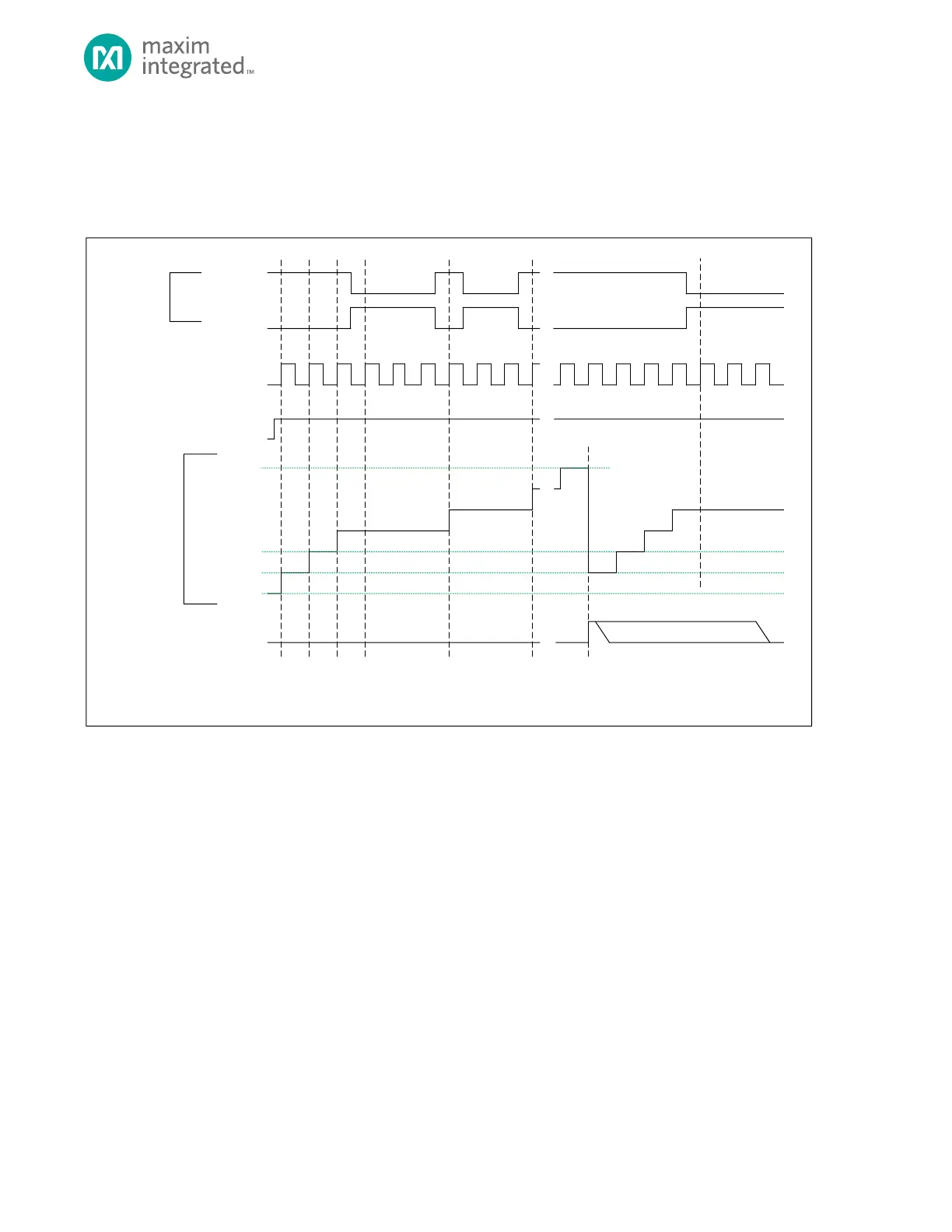
Figure 10-6: Gated Mode Diagram
TMR_CN.TEN
TMR_CNT
0X0000_0000**
0X0000_0001*
TMR_INT.IRQ
TIMER CL OCK
TMR_CMP
* TMR_CNT AUTOM ATICALLY RELOADS WITH 0X0000_0001 AT THE END OF THE TIMER PERIOD, BUT SOFTWARE CAN WRITE ANY INITIAL VALUE TO TMR_CNT
BEFORE THE TIMER IS ENABLE D.
** THE DEFAULT VALUE OF TM R_CNT FOR THE FIRST PERIOD AFTER A SYSTEM RE SET IS 0X0000_0000 UNLESS CHA NGED BY SOFTWARE .
TMR_CN.TPL = 1
TMR_CN.TPL = 0
TIMER PIN
(INPUT)
0X0000_0002
SOFTW ARE CLEARS BIT
10.10.1 Timer Period
The timer period ends when TMRn_CNT = TMRn_CMP.
The timer peripheral automatically performs the following actions at the end of the timer period:
1. TMRn_CNT is reset to 0x0000 0001. The timer remains enabled and continues incrementing.
2. The timer interrupt bit TMRn_INT.irq will be set. An interrupt will be generated if enabled.