MAX32660 User Guide
Maxim Integrated Page 38 of 195
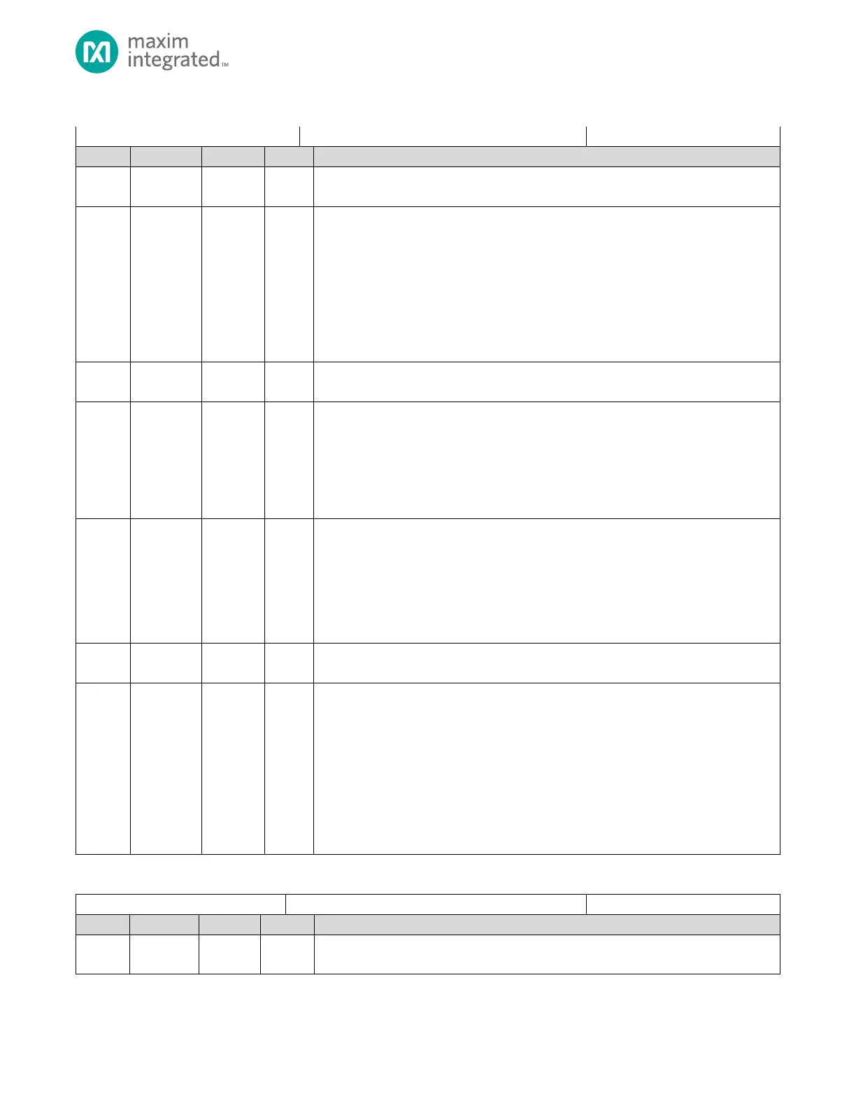
Table 4-16: Power Management Register
Power Management Register
Reserved for Future Use
Do not modify this field.
HFIO DEEPSLEEP Auto Off
When set, the High-Frequency Internal Oscillator is automatically powered off when in
DEEPSLEEP mode. If the HFIO is not enabled, GCR_CLK_CTRL.hirc_en = 1, when entering
DEEPSLEEP mode, the value of this field is ignored.
0: HFIO oscillator is active, powered on, during DEEPSLEEP mode if the HFIO is enabled
(GCR_CLK_CTRL.hirc_en = 1).
1: HFIO Oscillator is powered off in DEEPSLEEP mode.
Note: This field should be set to 1 prior to entering DEEPSLEEP mode to achieve the lowest
power numbers for the device if the HFIO is enabled (GCR_CLK_CTRL.hirc_en = 1).
Reserved for Future Use
Do not modify this field.
RTC Alarm Wakeup Enable
When this field is set to 1, If the RTC is configured to generate a wakeup alarm, an RTC
wakeup event causes the MAX32660 to exit all low power modes and transition directly
to ACTIVE mode. Refer to section 9.2.3 RTC Wakeup From DEEPSLEEP/BACKUP Power
Modes for details on enabling the RTC as a wakeup source.
0: Wakeup from RTC disabled, regardless of the RTC alarm configuration.
1: Wakeup from RTC alarm enabled.
GPIO Wakeup Enable
When enabled, activity on any GPIO pin configured for wakeup causes an exit from SLEEP
and DEEPSLEEP low power modes and transitions directly to ACTIVE mode.
0: Wakeup from GPIO disabled, regardless of the GPIO wakeup configuration.
1: Wakeup from GPIO enabled.
Note: Refer to section 6.4.2: Using GPIO for Wakeup from Low Power Modes for
additional details.
Reserved for Future Use
Do not modify this field.
Operating Mode
Configures the current operating mode for the device.
0: ACTIVE mode
1: Reserved for Future Use
2: Reserved for Future Use
3: Reserved for Future Use
4: BACKUP Low Power Mode
5: Reserved for Future Use
6: Shutdown Mode
Note: All other values are Reserved for Future Use.
Table 4-17: Peripheral Clock Disable 0 Register
Peripheral Clocks Disable 0 Register
Reserved for Future Use
Do not modify this field.