MAX32660 User Guide
Maxim Integrated Page 132 of 195
For all of the above roles, the Master is responsible for initiating the transfer and generating the clock signal on the SCL line.
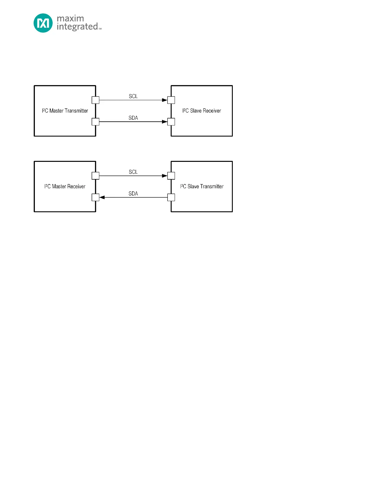
Figure 12-1, below, shows the four roles and the direction of the communication on the SCL and SDA lines.
Figure 12-1: The Roles of I
2
C Devices and the Direction the I
2
C Signals
12.2 I
2
C Master/Slave Features
Each I
2
C Master/Slave is compliant with the I
2
C Bus Specification and include the following features
• Compliant with I
2
C bus specification revision 06 (2014)
• Information transferred via a serial data bus (SDA) and a serial clock line (SCL)
• Operates as either a master or slave device as a transmitter or receiver
• Supports I
2
C Standard Mode, Fast Mode, Fast Mode Plus and High Speed (Hs) mode
• Data transfer rates up to:
100 kbps in Standard Mode
400 kbps in Fast Mode
1 Mbps in Fast Mode Plus
3.4 Mbps in Hs Mode
• Multi-master capable, including support for arbitration and clock synchronization for Standard, Fast and Fast Plus
modes
• Supports the maximum bus capacitance as defined by the I
2
C bus specification
• Supports 7- and 10-bit addressing
• Supports RESTART condition
• Supports clock stretching
• Support for 7- and 10-bit device addressing
• Transfer status interrupts and flags
• DMA data transfer support
• I
2
C timing parameters fully controllable via firmware
• Glitch filter and Schmitt trigger hysteresis on SDA and SCL
• Control, status, and interrupt events are available for maximum flexibility
• Independent 8-byte RX FIFO and 8-byte TX FIFO
• TX FIFO preloading
• Programmable interrupt threshold levels for the TX and RX FIFO


 To Next Page