MAX32660 User Guide
Maxim Integrated Page 186 of 195
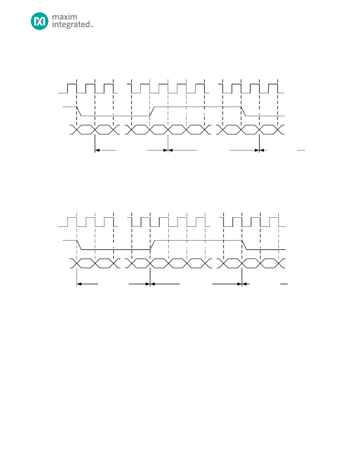
Figure 14-3: I
2
S Audio Data in Standard I
2
S Operation
Figure 14-4: I
2
S Mode (i2s_en=1, i2s_lj=1)
14.5 SPI and I
2
S Error Detection
The SPIMSS peripheral includes error detection logic to recognize when communication errors occur for either SPI or I
2
S
communications. If the SPIMSS_CTRL.irqe bit is set to 1, error conditions generate a SPIMSS IRQ. The SPIMSS Interrupt Flag
Register, SPIMSS_INT_FL, includes the error flags described below.
14.5.1 Transmit Overrun
A transmit overrun error indicates a write to the transmit FIFO was attempted when the internal transmit FIFO was full in
either SPI or I
2
S modes. An overrun condition sets the SPIMSS_INT_FL.tovr bit to 1. Writing a 1 to SPIMSS_INT_FL.tovr clears
this error flag.
Note: A transmit FIFO overrun in I
2
S mode may result in mixing left and right channel data. Software should reinitialize the
DMA channel, the Transmit FIFO and restart the I
2
S transfer.