MAX32660 User Guide
Maxim Integrated Page 159 of 195
13 Serial Peripheral Interface 0 (SPI0)
The Serial Peripheral Interface 0 (SPI0) is a highly configurable, synchronous communications peripheral that interfaces to
SPI devices and supports both Master and Slave modes.
13.1 SPI Port 0
Features:
Four-Wire, full-duplex communication
• Three-Wire, half-duplex communication supported
• Selectable number of bits per character
1-bit to 16-bits
• Master and Slave mode support
• Wakeup from SLEEP based on configurable Transmit and Receive FIFO Levels
• Four SPI modes (mode 0, 1, 2, and 3)
• Programmable Serial Clock (SCK) frequency and duty cycle
• Master mode operation up to 60MHz
• Slave mode operation up to 48MHz
• Independent clock phase and clock polarity control enabling support for SPI Mode 0, 1, 2, and 3
• 32-byte Transmit FIFO, 32-byte Receive FIFO
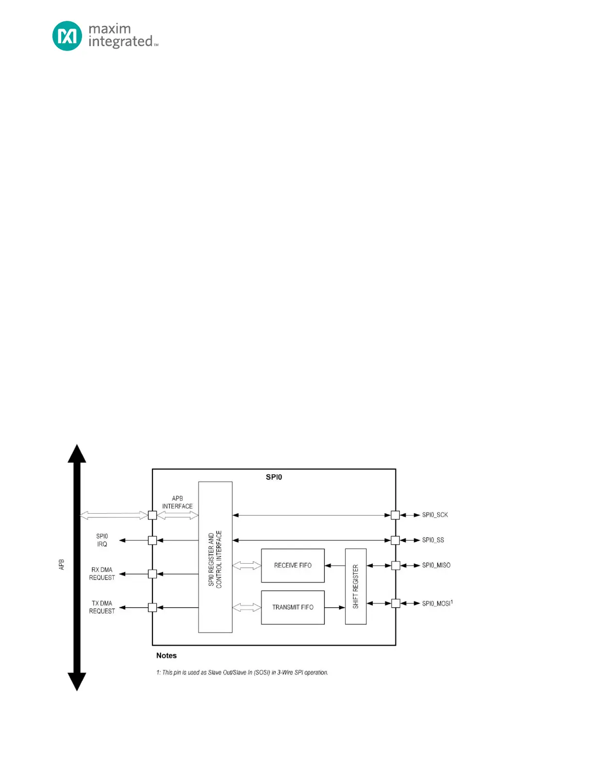
The SPI0 Peripheral are independently configurable as for master or slave operation. A SPI network uses a single master
with one or more slave devices for a given transaction. A high level block diagram of the SPI0 peripheral is shown in Figure
13-1, below.
Figure 13-1: SPI0 Block Diagram
z
 Loading...