MAX32660 User Guide
Maxim Integrated Page 160 of 195
13.2 Overview
13.2.1 Four-Wire SPI Signals
SPI devices operate as either a Master or Slave device. In four-wire SPI, four signals are required for communication as
shown in Table 13-1, below.
Table 13-1: Four-Wire SPI Signals
The master generates the Serial Clock signal, which is an
output from the master and an input to the slave.
Master Output Slave Input
In master mode, this signal is used as an output for
sending data to the Slave. In slave mode this is the input
data from the Master.
Master Input Slave Output
In master mode, this signal is used as an input for
receiving data from the Slave.
In slave mode, this signal is an output for transmitting
data to the Master.
In master mode, this signal is an output used to select a
slave device prior to communication.
In slave mode, this signal is an input used to indicate the
Master is going to start communication.
The MAX32660 supports a single slave select pin, SPI0_SS0, for SPI0.
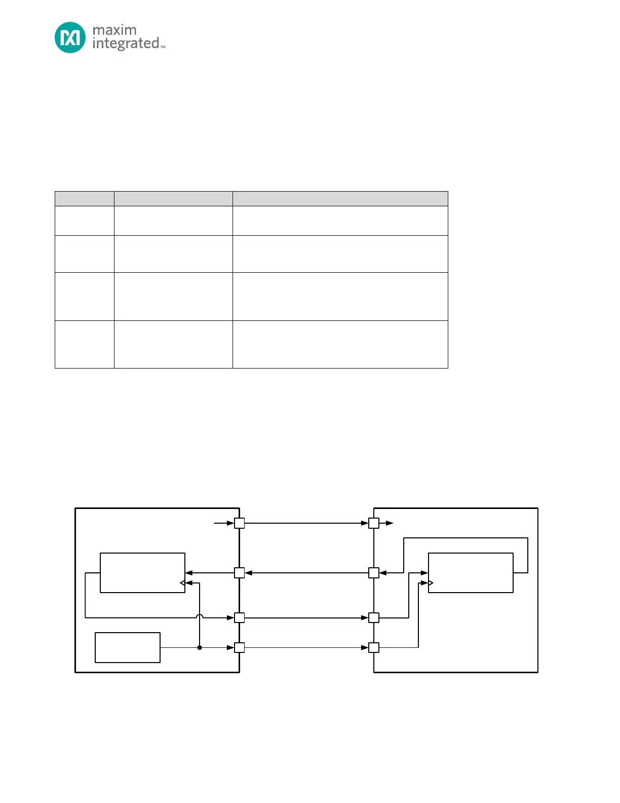
A typical four-wire SPI network is shown in Figure 13-2, below. In a typical SPI network, the master device selects the slave
device using the slave select output. The master starts the communication by selecting the slave device by asserting the
deasserted, the device is required to put the SPI pins in tri-state mode.
Figure 13-2: 4-Wire SPI Connection Diagram