MAX32660 User Guide
Maxim Integrated Page 117 of 195
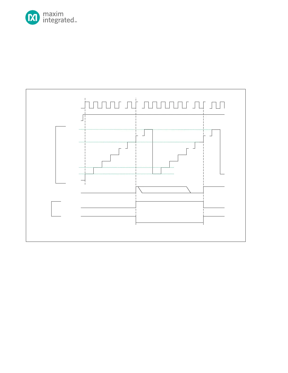
10.9 Compare Mode (101b)
In Compare mode the timer peripheral increments continually, allowing the timer to be a programmable 32-bit
programmable period timer. The end of timer period event occurs when the timer value matches the compare value, but
the timer continues to increment until the count reaches 0xFFFF FFFF. The timer counter then rolls over and continues
counting from 0x0000 0000.
Figure 10-5: Counter Mode Diagram
TMR_CN.TEN
TMR_CNT
0X0000_0000**
0X0000_0001*
TMR_INT.IRQ
TIMER CLOCK
TMR_CN.CMP
* TMR_CNT AUTOMATICALLY RELOADS WITH 0X0000_0001 AT THE END OF THE TIMER PERIOD, BUT SOFTWARE CAN WRITE ANY INITIAL VALUE TO TM R_CNT
BEFORE THE TIMER IS ENABLED.
** THE DEFAULT VALUE OF TM R_CNT FOR THE FIRST PE RIOD AFTER A SY STEM RESET IS 0X0000_0000 UNLESS CHANGED BY SOFTWARE .
SOFTW ARE CLEARS .IRQ BIT
0XFFFF_FFFF
TMR_CN.TPL = 1
TMR_CN.TPL = 0
TIMER PIN
(OUTPUT)
0X0000_0002
10.9.1 Timer Period
The timer period ends on the timer clock following TMRn_CNT = TMRn_CMP.
The timer peripheral automatically performs the following actions at the end of the timer period:
1. The timer remains enabled and continues incrementing. Unlike other modes, TMRn_CNT is not reset to
0x0000 0001 at the end of the timer period.
2. If the timer output is enabled, then the timer pin toggles state (low to high or high to low).
3. The timer interrupt bit TMRn_INT.irq will be set. An interrupt will be generated if enabled.
 Loading...