MAX32660 User Guide
Maxim Integrated Page 122 of 195
10.12 Timer Registers
Each timer is controlled by a block of registers assigned to that specific timer. All timers contain an identical set of registers.
Register names for a specific instance are defined by appending the instance number to the peripheral name. For example,
the Timer Count Register for Timer 0 is TMR0_CNT while the Timer Count Register for Timer 1 is TMR1_CNT, and so on. The
MAX32660 includes three timer instances, TMR0, TMR1 and TMR2.
The base address for TMR0, TMR1 and TMR2 are as follows:
• TMR0: 0x4001 0000
• TMR1: 0x4001 1000
• TMR2: 0x4001 2000
Refer to Table 3-1: APB Peripheral Base Address Map for the addresses of all APB mapped peripherals.
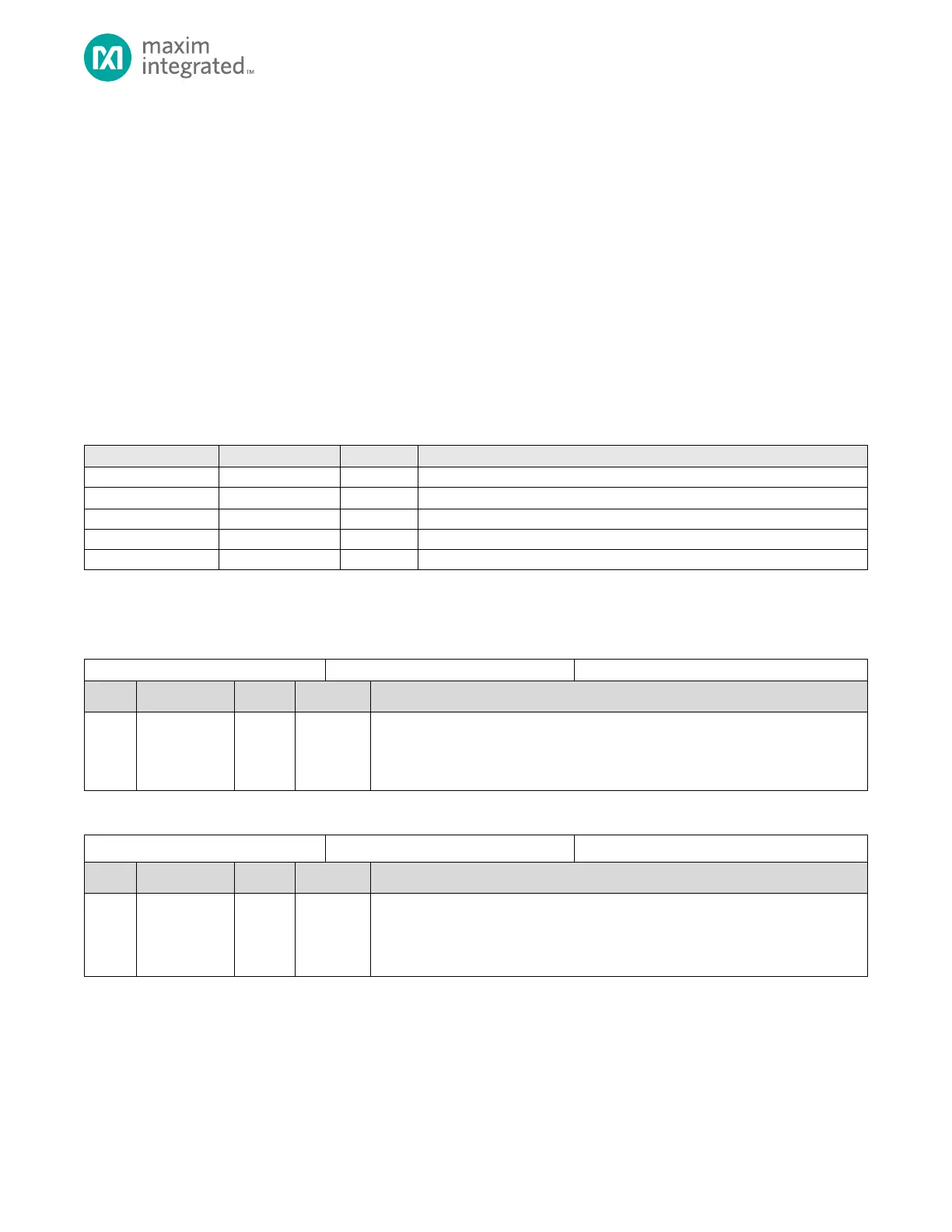
Table 10-1: Timer Register Offsets, Names, Access and Descriptions
Count
The current count value for the timer. This field increments as the timer counts.
Reads to this register are always valid. In general, disable the timer by clearing bit
TMRn_CN.ten, prior to writing the TMRn_CNT field.
Timer Compare Value
The compare field meaning is determined by the specific mode of the timer. Refer to
detailed configuration section for compare usage and meaning.

 Loading...