MAX32660 User Guide
Maxim Integrated Page 51 of 195
5 Flash Controller
The MAX32660Flash Controller is a peripheral that manages read, write, and erase accesses to the internal flash.
5.1.1 Features
• Up to 256KB total internal flash memory
32 pages
8,192 bytes per page
2,048 words by 128 bits per page
• 128-bit data reads
• 32-bit or 128-bit write support
• Page erase and mass erase support
• Write Protection
5.2 Overview
The MAX32660 contains 256KB of internal flash memory for storing user application and data. The internal flash memory is
programmable via the JTAG debug interface (in-system) or directly with user application code (in-application).
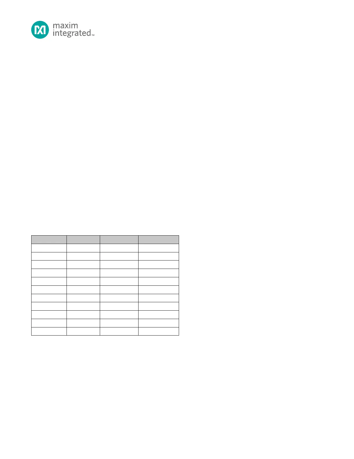
The flash is organized as an array of pages. Each page is 8,192 bytes per page. Table 5-1, below, shows the start address and
end address for the internal flash memory. The internal flash memory is mapped with a start address of 0x0000 0000 and
an end address of 0x0003 FFFF for a total of 256KB.
Table 5-1: Internal Flash Memory Organization
5.3 Usage
The Flash Controller manages write and erase operations for internal flash memory and provides a lock mechanism to
prevent unintentional writes to the internal flash. In-application and in-system programming, page erase and mass erase
operations are supported.
5.3.1 Clock Configuration
The Flash Controller requires a 1MHz peripheral clock for operation. The input clock to the Flash Controller block is the
system clock,
Use the Flash Controller clock divisor to generate
, as shown in Equation 5-1,