MAX32660 User Guide
Maxim Integrated Page 67 of 195
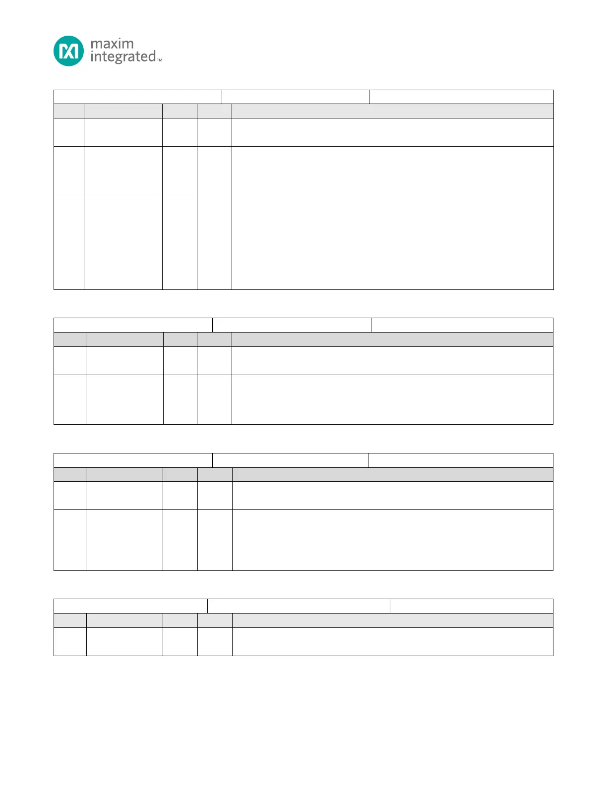
Table 6-19: GPIO Pullup/Pulldown Enable Register
GPIO Pullup Pulldown Selection 0 Register
Reserved for Future Use
Do not modify this field.
GPIO Pull Up/Pull Down Enable
Setting this bit to 1 enables either the weak pull-up or weak pull-down resistor on the
respective pin. The selection for pull-up or pull-down resistor is set using the
GPIO_PULL_SEL register.
GPIO Pull Down Enable
Setting this bit to 1 enables the weak pull-down resistor on the respective I/O pin.
GPIO with I
2
C as an alternate function do not support a weak pull-up resistor. If either
of the GPIO_PULL_SEL[9:8] bits are set to 1, setting the same bit in this register has no
effect.
0: Pull down resistor disable.
1: Pull down resistor enabled if respective bit in GPIO_PULL_SEL register is set to 0.
No effect if respective bit in GPIO_PULL_SEL register is set to 1.
Table 6-20: GPIO Alternate Function Select Register
GPIO Alternate Function Select Register
Reserved for Future Use
Do not modify this field.
GPIO Alternate Function 1 Mode Select
This bit combined with the corresponding bit in the GPIO0_AF0_SEL register set the
I/O pin to GPIO mode or to Alternate Function 1, 2, or 3. Refer to Table 6-5: GPIO
Mode and Alternate Function Selection for details on selection.
Table 6-21: GPIO Input Hysteresis Enable Register
GPIO Input Hysteresis Enable Register
Reserved for Future Use
Do not modify this field.
GPIO Input Hysteresis Enable
Setting a bit to 1 enables a Schmitt input to introduce hysteresis for better noise
0: Input pin uses a standard CMOS input.
1: Schmitt input enabled.
Table 6-22: GPIO Slew Rate Enable Register
GPIO Slew Rate Select Register
Reserved for Future Use
Do not modify this field.