MAX32660 User Guide
Maxim Integrated Page 71 of 195
7 DMA Controller
The Direct Memory Access controller (DMAC) is a hardware feature that moves data blocks from peripheral to memory,
memory to peripheral, and memory to memory. This data movement reduces the processor load significantly.
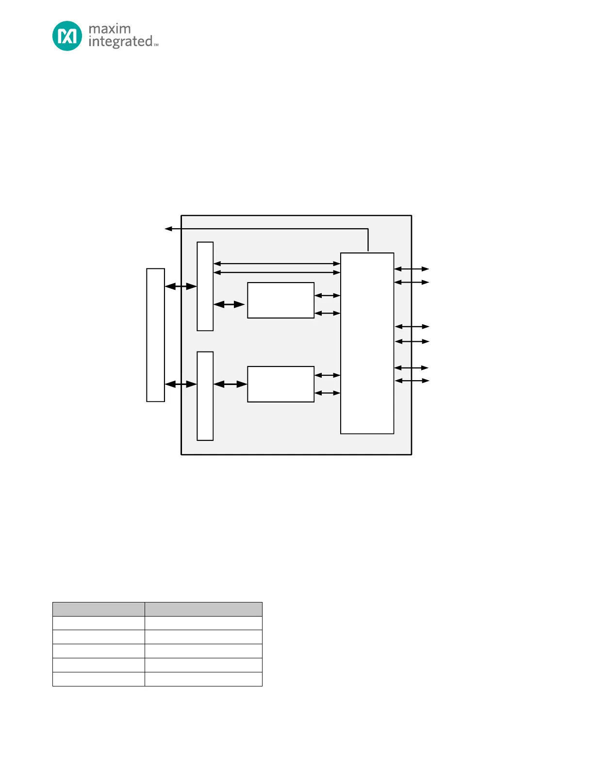
Figure 7-1 provides a high-level overview of the major DMA Controller components.
Figure 7-1: DMAC Block Diagram
All direct memory access (DMA) transactions consist of an advanced high-performance bus (AHB) burst read from the
source into the DMA FIFO followed by an AHB burst write from the DMA FIFO to the destination.
7.1 DMA channel operation
The DMA Controller has 4 channels. Each channel is governed by the registers shown in Table 7-1.
Table 7-1: DMA Channel Registers