MAX32660 User Guide
Maxim Integrated Page 40 of 195
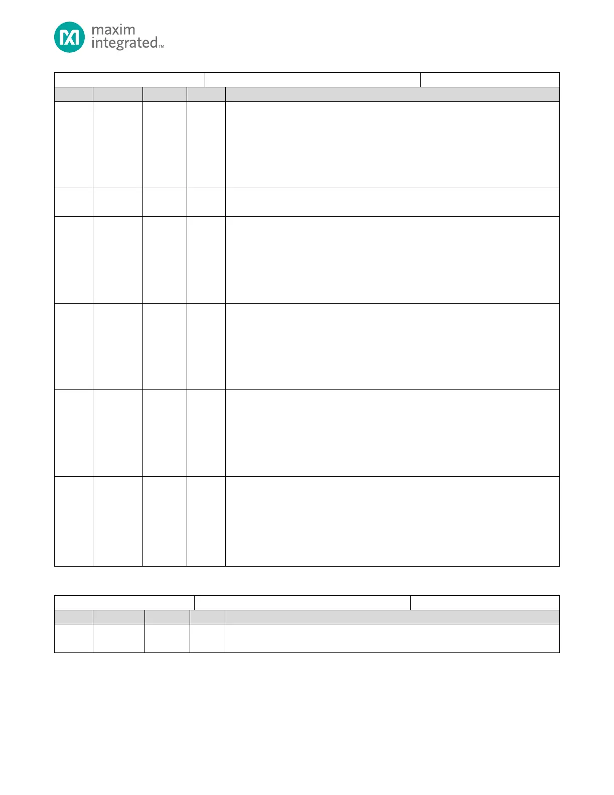
Peripheral Clocks Disable 0 Register
UART0 Clock Disable
Setting this field disables the APB clock to this peripheral. When the clock is disabled, the
peripheral power consumption is reduced, and the peripheral is disabled. Disabling the
Write 1 to disable, set to 0 to enable.
0: Peripheral Enabled
1: Peripheral Disabled
Reserved for Future Use
Do not modify this field.
SPI1 Clock Disable
Setting this field disables the APB clock to this peripheral. When the clock is disabled, the
peripheral power consumption is reduced, and the peripheral is disabled. Disabling the
clock to the peripheral does not affect the
Write 1 to disable, set to 0 to enable.
0: Peripheral Enabled
1: Peripheral Disabled
SPI0 Clock Disable
Setting this field disables the APB clock to this peripheral. When the clock is disabled, the
peripheral power consumption is reduced, and the peripheral is disabled. Disabling the
Write 1 to disable, set to 0 to enable.
0: Peripheral Enabled
1: Peripheral Disabled
Standard DMA Clock Disable
Setting this field disables the APB clock to this peripheral. When the clock is disabled, the
peripheral power consumption is reduced, and the peripheral is disabled. Disabling the
Write 1 to disable, set to 0 to enable.
0: Peripheral Enabled
1: Peripheral Disabled
Reserved for Future Use
Do not modify this field.
GPIO0 Port and Pad Logic Clock Disable
Write 1 to disable, set to 0 to enable. Disabling the GPIO Port and Pad Logic gates off the
clock from the GPIO Port and the individual GPIO pads.
0: Peripheral Enabled
1: Peripheral Disabled
Table 4-18: Memory Clock Control Register
Memory Clock Control Register
Reserved for Future Use
Do not modify this field.