MAX32660 User Guide
Maxim Integrated Page 161 of 195
13.2.2 Three-Wire SPI Signals
Three-wire SPI is supported by the MAX32660 family of microcontrollers. In this variant the MOSI and MISO lines are
combined and used as a bi-directional half-duplex communication pin. Three-wire also uses a serial clock generated by the
master and a slave select pin controlled by the master. Table 13-1 describes each of the signals used in three-wire SPI
communication.
Table 13-2: Three-Wire SPI Signals
The master generates the Serial Clock signal, which is an
output from the master and an input to the slave.
This is a half-duplex, bidirectional I/O pin used for
communication between the SPI master and slave in a
three-wire SPI communication network
In master mode, this signal is an output used to select a
slave device prior to communication.
In slave mode, this signal is an input used to indicate an
external SPI master is starting communication.
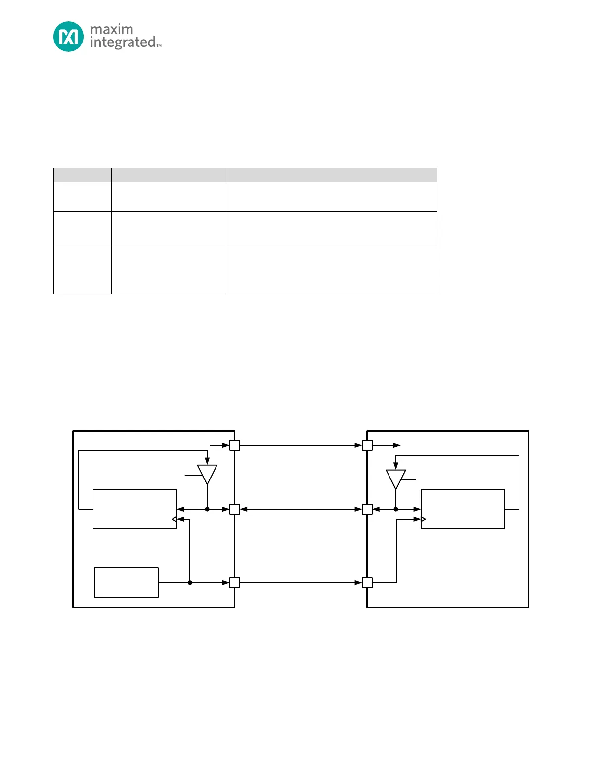
A three-wire SPI network is shown in Figure 13-3, below. The master device selects the slave device using the slave select
output. The communication starts with the master asserting the slave select line and then starting the clock (SCK). In a 3-
Wire SPI communication, the master and slave must both know the intended direction of the data. For a write, the master
drives the data out the SISO pin. For a read, the master must release the SISO line and let the slave drive the SISO line. In
the MAX32660 the direction of transmission is controlled using the FIFO enables. See Three-Wire SPI Read and Write for
detailed information.
Figure 13-3: 3-Wire SPI Connection Diagram
13.3 SPI Configuration
Before configuring the SPI peripheral, first disable the SPI port by setting SPI0_CTRL0.spi_en to 0.