MAX32660 User Guide
Maxim Integrated Page 131 of 195
12 I
2
C Master/Slave Serial Controller
The MAX32660 integrates two I
2
C peripherals, designated I2C0 and I2C1. The register interfaces for I2C0 and I2C1 are
identical with the same offset addresses for each register. For simplicity, I2Cn is used throughout this section to refer to
both I
2
C ports (where n = [0,1]). The I2Cn peripheral supports High-speed mode (Hs-mode), Fast-mode and Standard mode
communication speeds. Each I2Cn peripheral can operate as a master or a slave device.
The I
2
C bus is a standardized two-wire, bidirectional serial bus. It uses only two bus lines, a Serial Data Access (SDA) line for
data, and a Serial Clock line (SCL) for the clock. SDA and SCL idle high with external pullup resistors. They are pulled low by
open-drain drivers in the peripherals. Internal pullup circuits in the GPIO pins are capable of holding the SDA line and SCL
line at a logic high state when all devices are idle, but external pullup resistors are highly recommended for all but the
simplest, lowest-capacitance systems.
An I
2
C master owns the I
2
C bus for the duration of a transfer, driving the clock (SCL) and generating START and STOP signals.
In slave mode, the I
2
C Controller relies on an external master to generate the clock on SCL. An I
2
C slave responds to data
and commands only when an I
2
C master device addresses it.
For detailed information on I
2
C bus operation refer to Maxim Application Note 4024: SPI/I²C Bus Lines Control Multiple
Peripherals.
12.1.1 Related Documentation
For details of the I
2
C-bus, please refer to the I
2
C-bus specification and user manual, Rev. 6 - 4 April 2014.
12.1.2 I
2
C Bus Terminology
Table 12-1, below, contains terms and definitions used in this chapter for the I
2
C Bus Terminology.
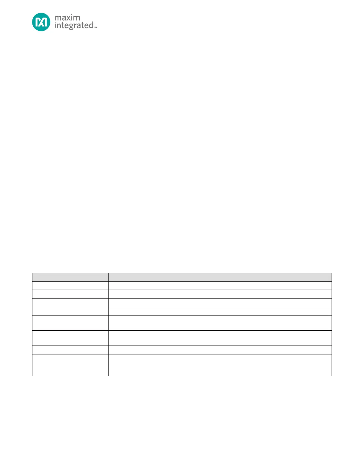
Table 12-1: I
2
C Bus Terminology