MAX32660 User Guide
Maxim Integrated Page 157 of 195
Hs-Mode Clock High Time
This field sets the Hs-Mode clock low count. In Slave mode, this is the time SCL is held
low after data is output on SDA. The following equation defined the clock low time.
Note: Refer to section JL:KIJ:KLJ:LKJ:KLJ:L for details on the requirements for the Hs-
mode clock high and low times.
Hs-Mode Clock Low Time
This field sets the Hs-Mode clock low count. In Slave mode, this is the time SCL is held
low after data is output on SDA. The following equation defined the clock low time.
Note: Refer to section 12.13 SCL Clock Generation for Hs-Mode for details on the
requirements for the Hs-mode clock high and low times.
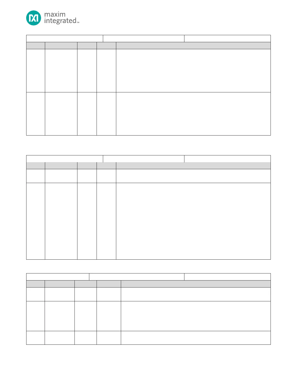
Table 12-20: I
2
C Timeout Registers
Reserved for Future Use
Do not modify this field.
Bus Error SCL Timeout Period
Set this value to the number of I
2
C clock cycles desired to cause a bus timeout error.
The I2Cn peripheral timeout timer starts when it pulls SCL low. After the I2Cn
peripheral releases the line, if the line is not pulled high prior to the timeout number
of I
2
C clock cycles, a bus error condition is set (I2Cn_INTFL0.toeri = 1) and the I2Cn
peripheral releases the SCL and SDA lines
0: Timeout disabled.
All other values result in a timeout calculation of:
Note: The timeout counter monitors the I2Cn controller’s driving of the SCL pin, not an
external I
2
C master driving the SCL pin.
Table 12-21: I
2
C Slave Address Register
I
2
C Slave Address Register
Reserved for Future Use
Do not modify this field.
Slave Mode Extended Address Select
When this I
2
C is operating in Slave Mode, this bit selects whether sla contains a 7-
bit or 10-bit address.
0: 7-bit addressing
1: 10-bit addressing
Reserved for Future Use
Do not modify this field.