MAX32660 User Guide
Maxim Integrated Page 78 of 195
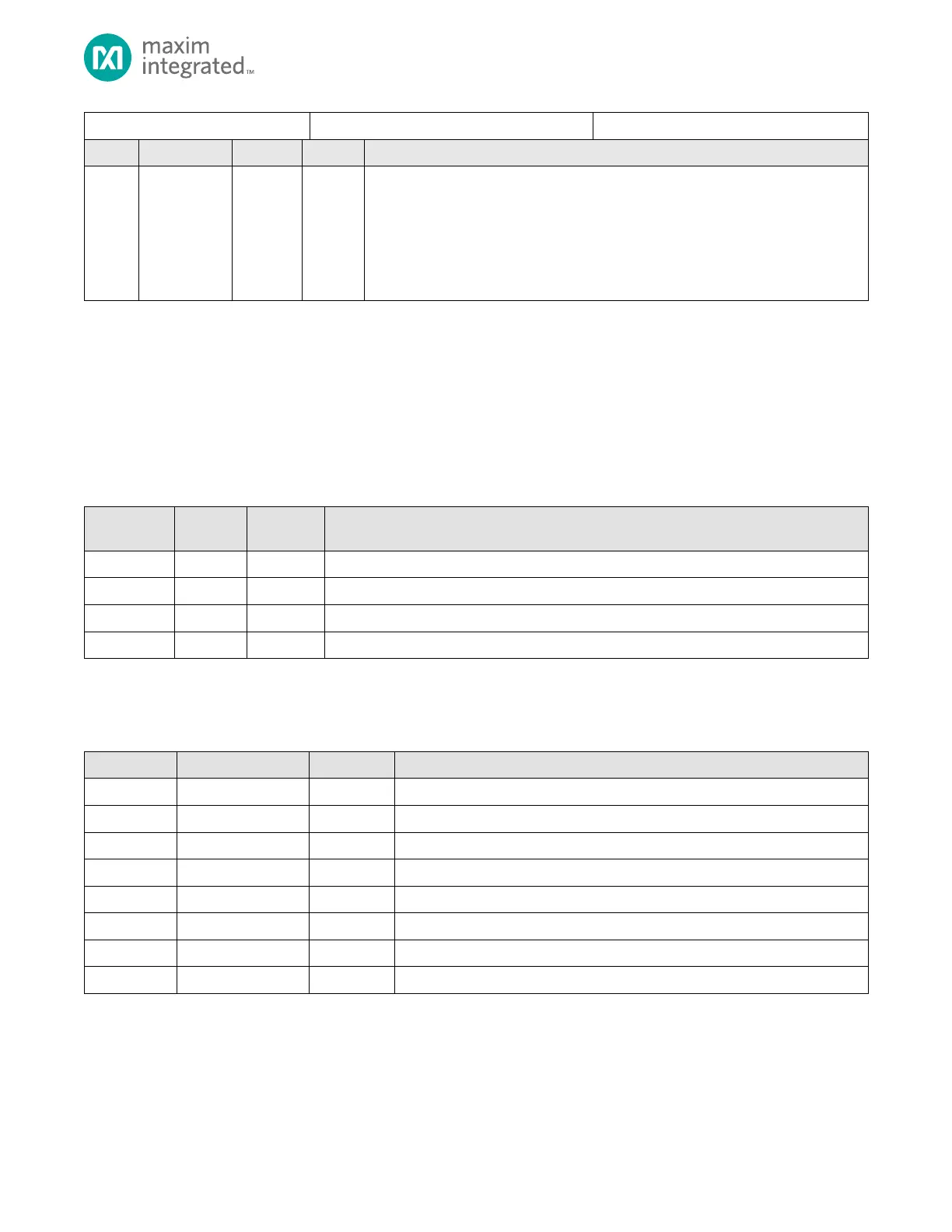
DMA Interrupt Flag Register
Channel Interrupt
Each bit in this field represents an interrupt for the corresponding channel. To clear an
interrupt, clear the corresponding active interrupt bit in the DMAn_STAT register. An
interrupt bit in this field is set only if the corresponding channel interrupt enable field
is set in the DMAn_CFG register.
0: No interrupt
1: Interrupt pending
7.14 Standard DMA Channel 0 to 3 Register Base Addresses
Each DMA channel has a set of associated Configuration Registers as shown in Table 7-10.
configuration registers requires adding the channel base address from Table 7-9 and the offset of the desired configuration
register from Table 7-10. For example,
Address, 0x4002 0160, plus the offset of the DMAn_DST_RLD register, [0x0018] which gives the address 0x4002 0178 for
DMA3_DST_RLD.
Table 7-9: Standard DMA Channel 0 to Channel 15 Offsets
7.15 Standard DMA Channel Configuration Register Offsets
Table 7-10: DMAn Channel Registers, Offsets, Access and Descriptions
DMA Channel Configuration Register
DMA Channel Status Register
DMA Channel Source Register
DMA Channel Destination Register
DMA Channel Count Register
DMA Channel Source Reload Register
DMA Channel Destination Reload Register
DMA Channel Count Reload Register