MAX32660 User Guide
Maxim Integrated Page 180 of 195
Note: The MAX32660 supports a single slave select pin in the SPIMSS peripheral for SPI1. This pin’s alternate function name
is SPI1_SS0.
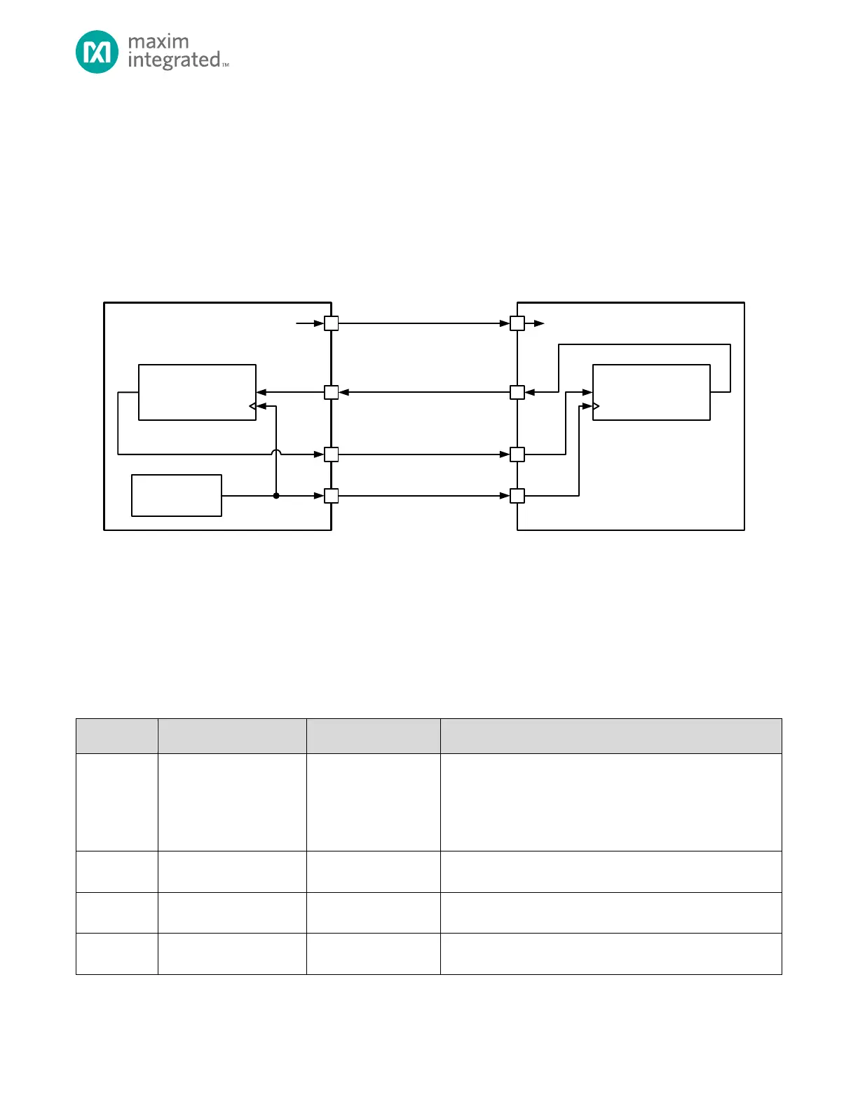
A typical four-wire SPI network is shown in Figure 14-2, below. In a typical SPI network, the master device selects the slave
device using the slave select output pin. The master starts the communication by selecting the slave device by asserting the
is
deasserted, the device is required to put the SPI pins in tri-state mode.
Figure 14-2: 4-Wire SPI Connection Diagram
14.1.3 I
2
S Signals
I
2
S devices operate as either a master or slave device. Three signals are required for communication as shown in Table 14-3,
below. For a slave I
2
S device, the SDI signal is used for audio input and the SDO pin is not required. For a master I
2
S device,
the SDO pin is used for audio output and the SDI pin is not required.
Table 14-2: I
2
S Signals
The word select clock indicates which channel is currently being
sent. I
2
S supports two channels, channel 1 and channel 2, left
and right respectively. The word select signal is often referred to
as left-right clock (LRCLK). Channel 1, the left audio, is
transmitted when the LRCLK is low. Channel 2, the right audio, is
transmitted when the LRCLK is high.
SCK is referred to as the Bit Clock, BCLK. The BCLK pulses once
for each discrete bit of data on the data lines.