MAX32660 User Guide
Maxim Integrated Page 115 of 195
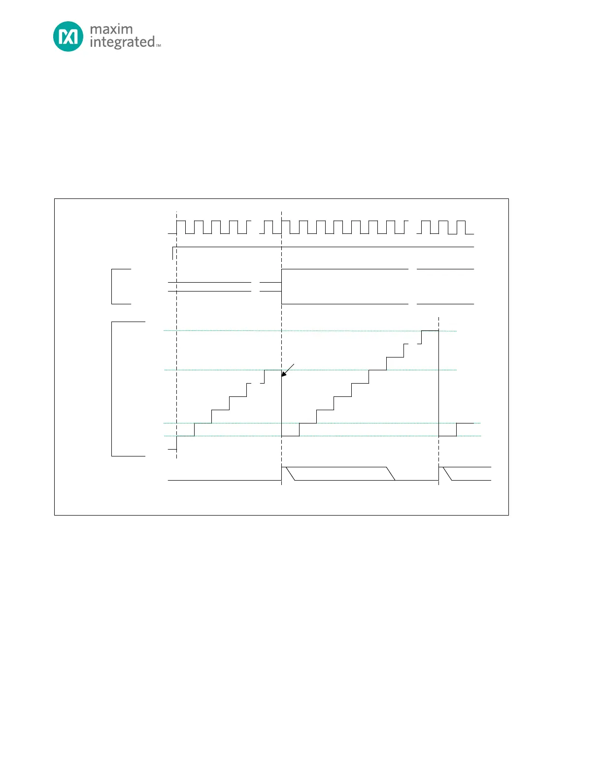
10.8 Capture Mode (100b)
Capture mode most often used to measure the time between events. The timer increments from an initial value until an
TMRn_CNT to the TMRn_PWM.pwm
register, resets TMRn_CNT = 0x0000 0001, and continues incrementing. Also, if the timer pin does not go active before
TMRn_CNT = TMRn_CMP, the timer will reset TMRn_CNT = 0x0000 0001, and continue incrementing. Either event will set
the timer interrupt bit.
Figure 10-4: Capture Mode Diagram
TMR_CN.TEN
TMR_CNT
0X0000_0000**
0X0000_0001*
TMR_INT.IRQ
TIMER CLOCK
TMR_CMP
* TM R_CNT AUTOM ATICALLY RELOADS WITH 0X0000_0001 AFTER A CAPTURE EVENT OR WHEN TMR_CNT = TMR_CMP, BUT SOFTWARE CAN WRI TE A NY INITIAL
VALUE TO TMR_CNT BEFORE THE TIM ER IS ENABLED.
** THE DEFAULT VALUE OF TMR_CNT FOR THE FIRST PERIOD AFTER A SY STEM RESET IS 0X0000_0000 UNLESS CHA NGED BY SOFTWARE.
SOFTW ARE CLEARS .IRQ BIT
TIMER PIN
(INPUT)
0X0000_0002
TMR_CNT
(CAPTURE)
TMR_CN.TPL = 1
TMR_CN.TPL = 0
TMR_CNT
(CAPTURE)
COP IED TO TMR_PWM
10.8.1 Timer Period
Two timer period events are possible in Capture Mode:
The Capture event occurs on the timer clock following the selected transition on the timer pin. The timer peripheral
automatically performs the following actions:
1. The value in TMRn_CNT is copied to TMRn_PWM
2. The timer interrupt bit TMRn_INT.irq will be set. An interrupt will be generated if enabled.
3. The timer remains enabled and continues incrementing.
4. The timer period ends on the timer clock following TMRn_CNT = TMRn_CMP.