MAX32660 User Guide
Maxim Integrated Page 111 of 195
10.6 Counter Mode (010b)
In Counter mode, the timer peripheral increments TMRn_CNT when a transition occurs on the timer pin. When TMRn_CNT
= TMR.CMP, the interrupt bit is set, TMRn_CNT is set to 0x0000 0001, and continues incrementing. The timer can be
configured to increment on either the rising edge or the falling edge, but not both.
The timer prescaler setting has no effect in this mode. The frequency of the timernput signal (f
CNT_CLK
) must not exceed 25
percent of the PCLK frequency as shown in the following equation:
Equation 10-4: Counter Mode Maximum Clock Frequency
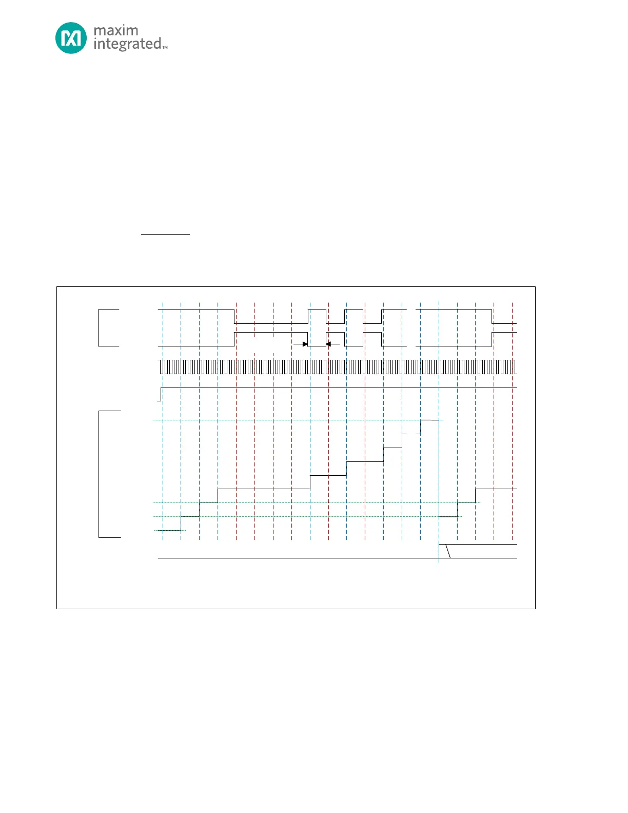
Figure 10-3: Counter Mode Diagram
TMR_CN.TEN
TMR_CNT
0X0000_0000**
0X0000_0001*
TMR_INT.IRQ
TMR_CN.CMP
* TMR_CNT AUTOMATICALLY RELOADS WITH 0X0000_0001 AT THE END OF THE TIMER PERIOD, BUT SOFTW ARE CAN WRITE ANY INITIAL VALUE TO TMR_CNT
BEFORE THE TIMER IS ENABLE D.
** THE DEFAULT VALUE OF TM R_CNT FOR THE FIRST PERIOD AFTER A SYSTEM RE SET IS 0X0000_0000 UNLESS CHA NGED BY SOFTWARE .
SOFTWARE CLEARS
TMR_CN.TPL = 1
TMR_CN.TPL = 0
TMR PIN
(INPUT)
0X0000_0002
PCLK
(INTERNAL)
MINIMUM INPUT
PULSE 4 * PCLK
10.6.1 Timer Period
The timer period ends on the rising edge of PCLK following TMRn_CNT = TMRn_CMP.
The timer peripheral automatically performs the following actions at the end of the timer period:
1. TMRn_CNT is reset to 0x0000 0001. The timer remains enabled and continues incrementing on selected transitions
of the timer pin.
2. The timer interrupt bit TMRn_INT.irq will be set. An interrupt will be generated if enabled.