MAX32660 User Guide
Maxim Integrated Page 43 of 195
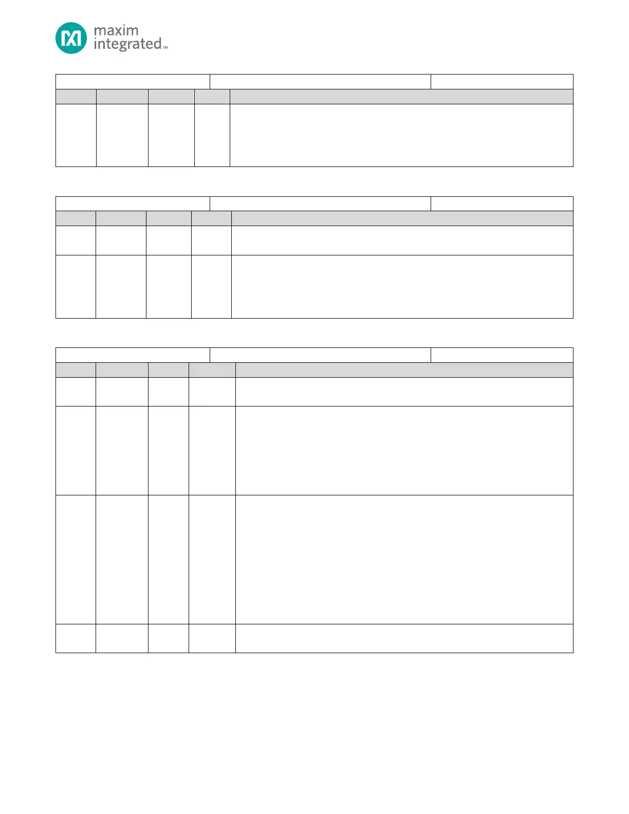
System Status Flag Register
Arm Cortex-M4 with FPU ICE Lock Status Flag
This field is set in the factory and if set to 1 disables JTAG SWD access to the device.
0: Arm ICE is unlocked and JTAG debug may be enabled using GCR_SCON.swd_dis field.
1: Arm ICE is locked (disabled), JTAG SWD is disabled and the GCR_SCON.swd_dis is
read-only.
Table 4-21: Reset Register 1
Reserved for Future Use
Do not modify this field.
I2C1 Reset
Write 1 to reset the peripheral state to the reset default state. When complete this field
will read 0.
0: I2C1 peripheral not in reset.
1: Write 1 to reset the I2C1 peripheral.
Table 4-22: Peripheral Clock Disable Register 1
Peripheral Clock Disable Register 1
Reserved for Future Use
Do not modify this field.
ICC Clock Disable
Setting this field disables the APB clock to this peripheral. When the clock is disabled,
the peripheral power consumption is reduced, and the peripheral is disabled. Disabling
the clock to the peripheral does not affect the
Write 1 to disable the icc clock disable.
0: ICC Clock Enabled
1: ICC Clock Disabled.
Flash Controller Disable
Setting this field disables the APB clock to this peripheral. When the clock is disabled,
the peripheral power consumption is reduced, and the peripheral is disabled. Disabling
Write 1 to disable the clock to the Flash Controller.
0: Flash Controller Clock Enabled
1: Flash Controller Clock Disabled.
Note: Disabling the clock to the Flash Controller prevents code fetches from the flash.
Care should be taken to ensure code execution is performed from RAM while the Flash
Controller peripheral clock is disabled.
Reserved for Future Use
Do not modify this field.