MAX32660 User Guide
Maxim Integrated Page 61 of 195
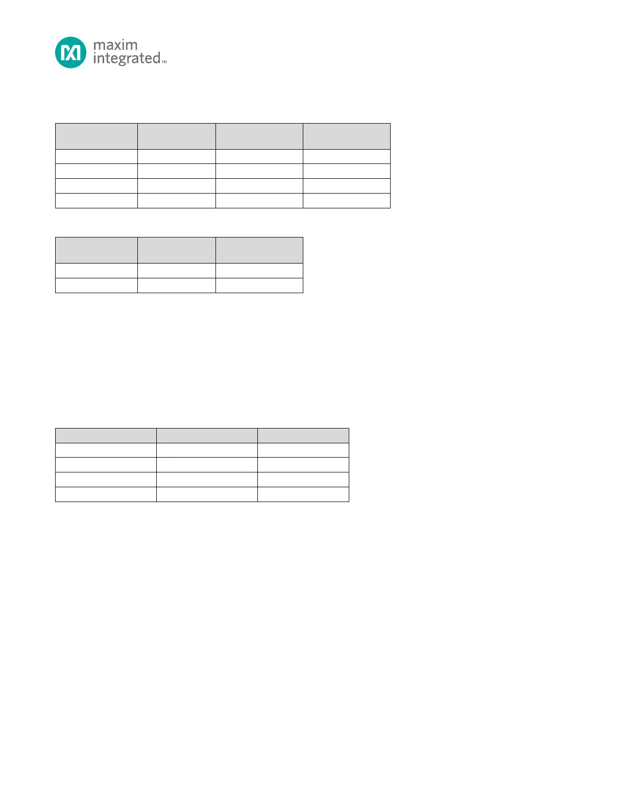
For GPIO with I
2
C as an Alternate Function, Table 6-4 shows the drive strength setting options.
Table 6-3: Standard GPIO Drive Strength Selection
Drive Strength
V
DD
= 1.62V
Drive Strength
V
DD
= 3.63V
Table 6-4: GPIO with I
2
C Alternate Function Drive Strength Selection
Drive Strength
V
DD
= 1.62V
Drive Strength
V
DD
= 3.63V
Note: The drive strength currents shown are targets only. Refer to the MAX32660 Data Sheet Electrical Characteristics table
for details of the V
OL_GPIO
, V
OH_GPIO
, V
OL_I2C
and V
OH_I2C
parameters.
6.3 Alternate Function Configuration
Table 6-5, below, shows the alternate function selection matrix. Write the GPIO0_AF0_SEL and GPIO0_AF1_SEL fields as
shown in the table to select the desired alternate function.
Table 6-5: GPIO Mode and Alternate Function Selection
Note: Each Alternate Function for a given peripheral is independently selectable. Mixing functions assigned to AF1, AF2 or
AF3 is supported if all of the peripheral’s required functions are enabled.
6.4 Configuring GPIO (External) Interrupts
Each GPIO supports external interrupt events when the GPIO is configured for I/O mode and the input mode is enabled. If
the GPIO is configured as a peripheral alternate function, the interrupts are peripheral controlled. GPIO interrupts can be