CONTROL SYSTEM
09–40–8
Flowchart
Example (PCM-related communication error)
Note
• This example is for MT with ABS.
1. DTCs for the PCM, ABS HU/CM and instrument cluster can be verified using a SST (WDS or equivalent).
END
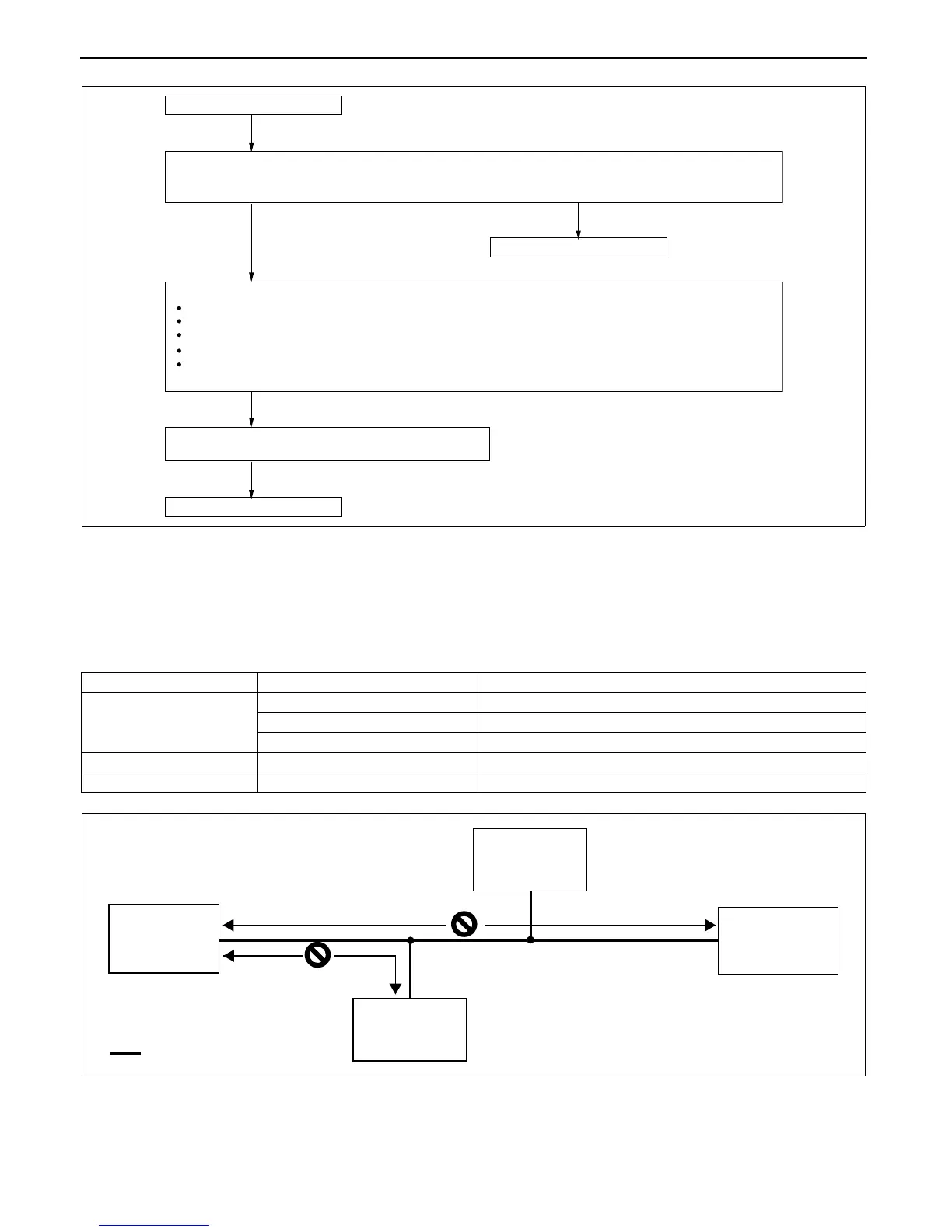
START
Verify that DTCs are displayed for PCM, TCM, ABS HU/CM, DSC HU/CM, EPS control module,
keyless control module, TPMS control module and instrument cluster.
Are any DTCs display?
Verify that PID/data monitor is displayed for instrument cluster.
See below table for DTC and malfunction location.
ABS_MSG
TCM_MSG
PCM_MSG
EPS_MSG
TPMS_MSG
Determine the malfunctioning part of the CAN system.
END
Ye s
No
CHU0940S005
Module Displayed DTC Probable malfunction location
PCM
U0073 PCM-related CAN system malfunction
U0121 Communication error between PCM and ABS HU/CM
U0155 Communication error between PCM and instrument cluster
ABS HU/CM U1900, U2516 ABS HU/CM-related CAN system malfunction
Instrument cluster U1900, U2516 Instrument cluster-related CAN system malfunction
PCM
INSTRUMENT
CLUSTER
ABS HU/CU
DLC-2
: TWISTED PAIR
NO GOOD
NO GOOD
CHU0940S003
 Loading...