In essence, you need to follow this procedure for configuring actions and mes-
sages for events:
• Step 1: Activate the camera's arming switch (Setup Menu > General Event
Settings); see section 7.5,
Arming
.
• Step 2: Activate and configure the desired events (Setup Menu > Event Set-
tings); see section 7.6,
Events
.
• Step 3: Activate, configure and assign an action or a message to this event
and configure the corresponding action or message profile (Setup Menu >
Actions or Setup Menu > Messaging); see section 7.7,
Actions and Mes-
sages, Action and Message Profiles
.
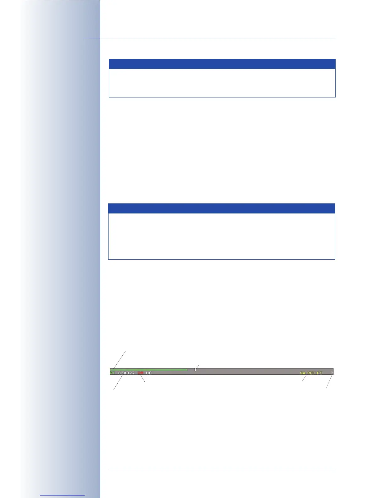
7.4 Screen Display of Event Settings in Live Image
All activated events, actions and messages are displayed at the bottom of the
camera's live image (Setup Menu > Text and Display Settings > Display
Options:
Symbols
). Activated events (event symbols) are displayed at the bottom
left corner, activated actions and messages (action and message symbols) are
displayed at the bottom right corner. Likewise, the status of the recording feature is
displayed at the bottom right corner.
For example, the VM UC symbols show that the Video Motion and User Click
events have been activated. The SD and VA symbols indicate activated Sound on
Event and Visual Alarm actions/messages. The REC symbol is displayed if
© MOBOTIX AG • Security-Vision-Systems • Made in Germany
www.mobotix.com • sales@mobotix.com • 10.10.2006
144/288
Software Camera Manual Part 2
The camera archives de-
tected events in its inter-
nal image storage
Procedure!
Activated Events, Actions
and Messages are dis-
played as symbols in the
live image
Event Symbols:
UC = User Click
VM = Video Motion
detection
Action Symbols:
VA: Visual Alarm
REC: Recording
FS: File Server
FT: FTP file transfer
Note
By factory default, the recorded images are stored in the internal
image storage of the MOBOTIX camera. For additional information on
this topic, see chapter 8,
Recording
.
Note
The camera's arming status as well as individual actions and mes-
sages can be controlled using the time table profiles (exact date/time)
or they can be controlled by one of the signal inputs (SI Low/SI High),
using a key switch, for example. For additional information on this
topic, see sections 7.5,
Time Tasks
, and 7.8.6,
Time Tables
.
Level meter with current Passive Infrared (PI) sensor value
Number of last event
Enabled events (red = currently active)
Enabled actions (yellow)
Remaining event dead time
Trigger value for creating an event