Motion Brake Module
5-83
5
Motion 4000
The four switches of DIP switch SW3 function as two independent pairs. Switches 3 and 4
enable various software features. Switches 1 and 2 set the ID for the module. The ID identifies
the module to the controller allowing it to be addressed and controlled independently of any
other modules used (up to three).
Reset Switch The reset switch, RST, resets the logic board processor.
Jumper JP1 JP1 enables/disables the CAN termination resistor.
• A position: Terminates the CAN connection on the board.
• B position: Leaves the CAN termination open on the board (Normal position for this
board).
ON LED
The ON LED next to the Reset switch is on solidly when the module is powered and functioning
properly. The ON LED will blink if a fault condition is detected. Under fault conditions, the LED
will blink a number of times, go dark for a period of time, and then repeat. The number of blinks
indicates the fault detected.
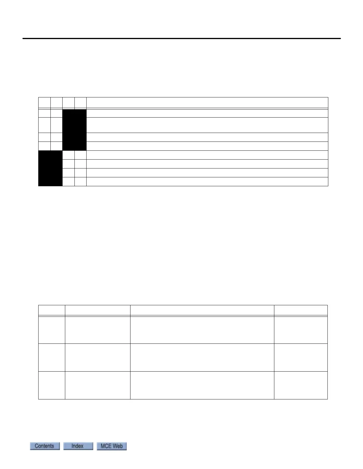
Table 5.31 SW3 Module ID and Software Features
1234 Description
Off Off
Brake module, ID=1 Primary brake module address
On Off
Brake module, ID=2 Secondary brake module address where module 1 controls the first
brake coil and module 2 controls a second brake coil on the same machine.
Off On
Brake module, ID=3 Emergency brake module address
On On
Module, ID=4 Future
Off Off unused
On Off unused
Off On Enables software update from EEPROM chip inserted in socket U21
On On unused
Table 5.32 LED Fault Indication
Blinks Fault Description Reset
1 Load over current If load current goes above 20A during the first 5 sec-
onds of operation or above 15A for 5 seconds during
operation, over current will be reported and current
will be limited to 15A.
Current reduction
2 Load over voltage If load voltage goes above 310VDC for more than 5
seconds, over voltage condition will be reported
through FLT output and voltage will be limited to
310V.
Voltage reduction
3 Aux IGBT stuck open If the brake is in pick, hold, or relevel mode and the
Aux IGBT monitoring circuit returns a high signal for
100mS or more, the Aux IGBT stuck closed fault will
occur.
Discrete: Proces-
sor reset.
CAN: Auto reset
after 8 seconds.