Troubleshooting
5-84 Manual # 42-02-2P24
Module Connectors Per Board
Top Board, TC-FCL This section provides information about user-accessible module
connections.
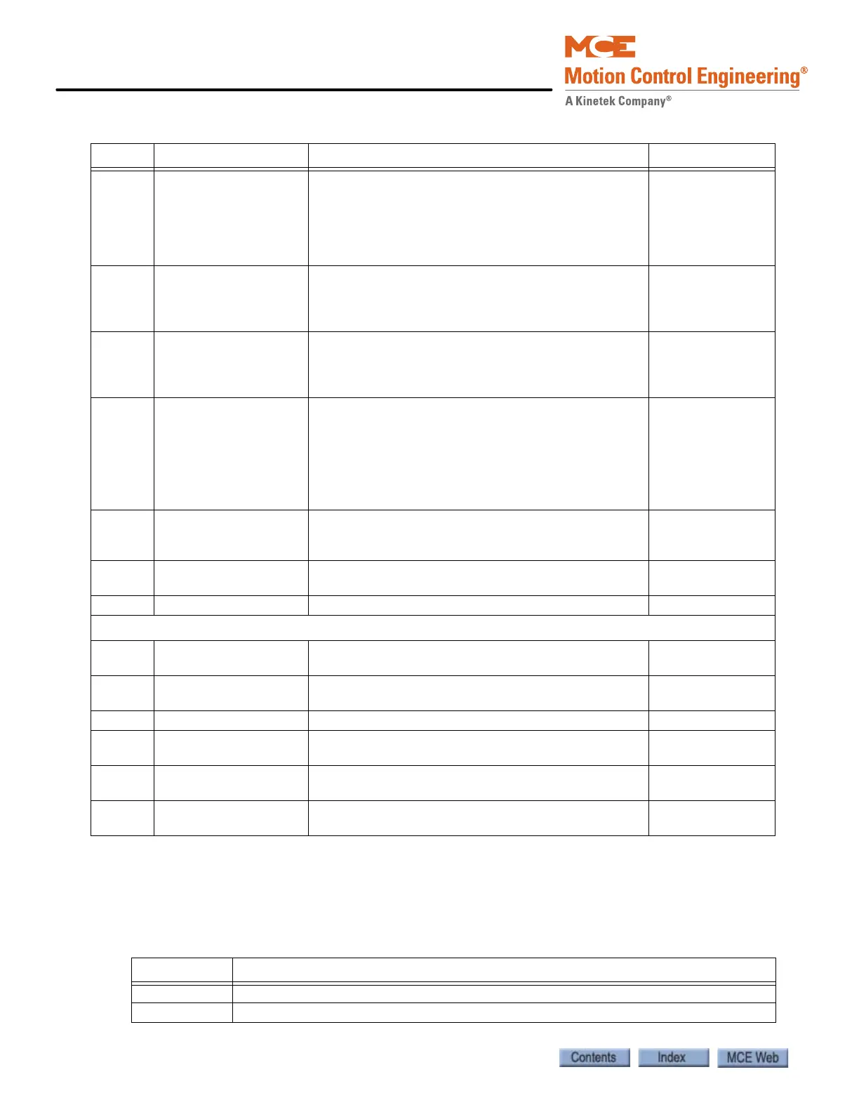
4 Aux IGBT stuck closed If the voltage across the Aux IGBT does not go high
enough to trigger the Aux IGBT monitoring circuit
during the dissipate mode, the Aux IGBT Stuck
closed fault will occur. This fault is scanned for after
the module switches from dissipate to inactive
mode.
Discrete: Proces-
sor reset.
CAN: Auto reset
after 8 seconds.
5 Main IGBT stuck open If the brake is in pick, hold, or relevel mode and
there is less than 5 volts or 100mA across the coil
for 200 mS or more, the IGBT stuck open fault will
occur.
Discrete: Proces-
sor reset.
CAN: Auto reset
after 8 seconds.
6 Main IGBT stuck closed If the brake is not in pick, hold, relevel, or dissipate
mode and there is more than 10 volts or 2 Amps
across the brake coil for 200 mS or more, the IGBT
stuck closed fault will occur.
Discrete: Proces-
sor reset.
CAN: Auto reset
after 8 seconds.
7 Module overheat The IGBT units on the bottom of the TC-FCP board
generate heat when operating. A thermal sensor on
the heat sink is connected to the module logic board
through the TS1 and TS2 inputs. If the temperature
becomes excessive, the logic module will generate a
fault, pulling the FLT output to the Common connec-
tion level and alerting the controller.
Temp e rat u r e
reduction.
8 Trying to run in manual
release mode
Manual brake pick is enabled. Remove from
manual brake pick
mode.
9 Bypass button stuck
closed
Brake bypass button stuck closed in manual pick
mode.
Check button.
10 Not used
CAN MODE ONLY
11 Discrete input during
CAN operation
Verify discrete pick, hold, and relevel inputs to J1 are
not used when CAN control is active.
Auto reset after 8
seconds.
12 Module address error. Verify SW1 positions for each module. 5-83. Auto reset after 8
seconds.
13 Not calibrated Module has not been calibrated Calibrate module
14 Load undercurrent Current <80% of learned Auto reset after 8
seconds.
15 Load undervoltage Voltage <80% of intended Auto reset after
seconds.
Continu-
ously
CAN disconnected CAN to module disconnected Troubleshoot con-
nection
Table 5.33 J1 Pin Assignment
Pin Function
PICK Discrete Pick control input from controller (V AC/DC)
HOLD Discrete Hold control input from controller (V AC/DC)
Table 5.32 LED Fault Indication
Blinks Fault Description Reset