Motion Brake Module
5-85
5
Motion 4000
J4, J5 J4 is a modular, CAN connector for serial module control. (See preceding informa-
tion about termination enabling jumper JP1.) J5 provides auxiliary connections that can be
used to directly lift the machine brake, regardless of controller status.
The level of the pick voltage is adjusted using potentiometer R67. The maximum pick voltage
range is determined by input voltage to the module and whether the input connection is single
phase, FCL1/FCL2, or three phase, FCL1/FCL2/FCL3.
J3 J3 provides control signals to the TC-FCP board and accepts feedback voltages from the
TC-FCP board.
J6 J6 accepts DC power voltages from the logic power supply board (TC-LPS).
Middle Board, TC-LPS
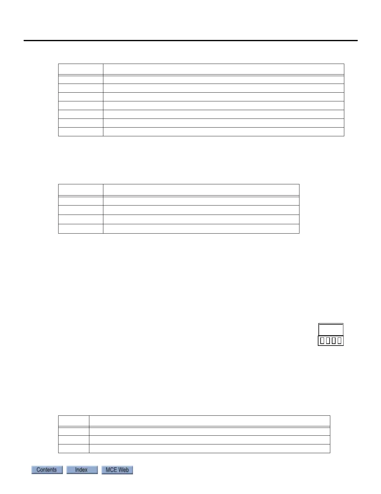
1 and 2 bus power connections from the controller are connected to TC-LPS connector
J1. As viewed from the front of the connector, pinout is:
This board provides DC power to the logic board through connector J2.
Bottom Board, TC-FCP
The FCP board transforms AC input power (single or three phase) into the DC output voltage
required to control the brake. The in-line connectors on the board are sized to handle higher
voltage and current.
RELEV Discrete Relevel control input from controller (V AC/DC)
FLT Overload fault output
COM Common connection for PICK, HOLD, RELEV, FLT
1 1 Bus (common) from elevator controller
2 2 Bus (120VAC) from elevator controller
TS2 Thermal switch input from sensor on module heat sink
TS1 Thermal switch input from sensor on module heat sink
Table 5.34 J5 Auxiliary Brake Connections
Pin Function
BRBP1 With BRBP3, connects to auxiliary brake pick switch
BRBP2 With BRBP4, energizes brake coil when active
BRBP3 With BRBP1, connects to auxiliary brake pick switch
BRBP4 With BRBP2, energizes brake coil when active
Table 5.35 In-Line Connectors Pin Assignment
Pin Function
J2, SN1 With SN2, connection point for external filter provided with unit
J2, SN2 With SN1, connection point for external filter provided with unit
J2, SN3 With J3, SN4, connection point for user-provided external filter
Table 5.33 J1 Pin Assignment
Pin Function