Magnetek Parameters Table
A-9
A
Motion 4000
Speed Command 9 Multi-Step Speed command #9 ft/m 0
Speed Command 10
Multi-Step Speed command #10 ft/m 0
Speed Command 11
Multi-Step Speed command #11 ft/m 0
Speed Command 12
Multi-Step Speed command #12 ft/m 0
Speed Command 13
Multi-Step Speed command #13 ft/m 0
Speed Command 14
Multi-Step Speed command #14 ft/m 0
Speed Command 15
Multi-Step Speed command #15 ft/m 0
A4 Power Convert
Id Reg Diff gain Flux Current regulator differential gain - 0.80 - 1.20 1.00
Id Reg Prop Gain Flux current regulator proportional gain - 0.20 - 0.40 0.30
Iq Reg Diff Gain Torque current regulator differential gain - 0.80 - 1.20 1.00
Iq Reg Prop Gain Torque current regulator proportional gain - 0.20 - 0.40 0.30
PWM Frequency Carrier frequency kHz 2.5 - 16.0 10.0
UV Alarm Level Level for undervoltage alarm % 80 - 99 80
UV Fault Level Level for undervoltage fault % 50 - 88 80
Extern Reactance External choke reactance % 0 - 10 0
Input L-L Volts Nominal line-line AC input Voltage, RMS volts 110 - 480 Drive dep.
A5 Motor
Motor ID Motor Identification - 4 Pole DFLT, 6
Pole DFLT,
MCE Test
MCE Test
Rated Mtr Power Rated motor output power HP 1.0 - 500 5.0
Rated Mtr Volts Rated motor terminal RMS voltage volts 190.0 - 575.0 460
Rated Excit Freq Rated excitation frequency Hz 5.0 - 400.0 60
Rated Motor Curr Rated motor current amps 1.00 - 800.00 6.8
Motor Poles Motor poles - 2 - 32 6
Rated Mtr Speed Rated motor speed at full load RPM 50.0 - 3000.0 1130
% No Load Curr Percent no load current % 10.0 - 60.0 45
Stator Leakage X Stator leakage reactance % 0 - 20.0 9.0
Rotor Leakage X Rotor leakage reactance % 0 - 20.0 9.0
Stator Resist Stator resistance % 0 - 20.0 1.5
Motor Iron Loss Iron loss at rated frequency % 0 - 15.0 0.5
Motor Mech Loss Mechanical loss at rated frequency % 0 - 15.0 1.0
Ovld Start Level Maximum continuous motor current % 100 - 150 110
Ovld Time Out Time that defines motor overload curve sec 5.0 - 120.0 60.0
Flux Sat Break Flux saturation curve slope change point % 0 - 100 75
Flux Sat Slope 1 Flux saturation curve slope for low fluxes % 0 - 200.0 0
Flux Sat Slope 2 Flux saturation curve slope for high fluxes % 0 - 200.0 50
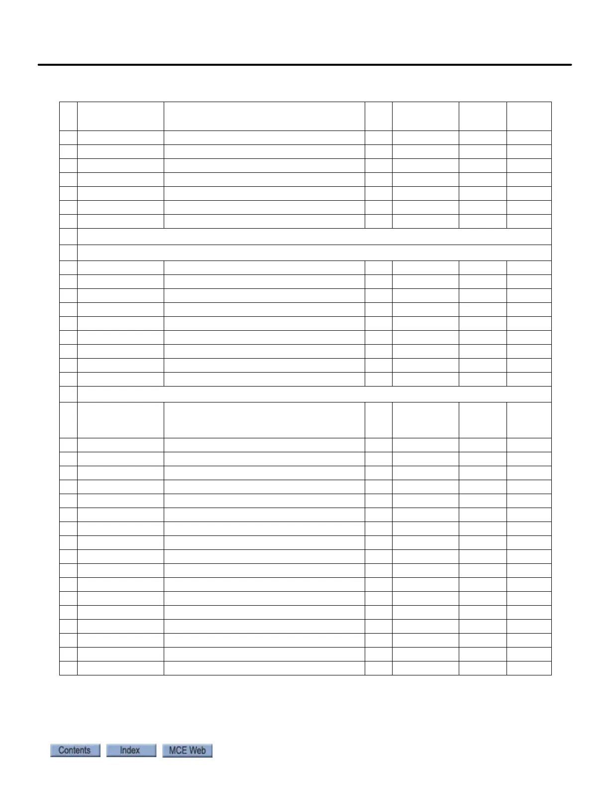
Table A.2 Magnetek AC Drive Table
#
Operator
Display
Parameter Description Unit
Setting
Range
MCE
Defaults
Field Set