16.4 Unit Memories (Input and Output Control Areas)
16-17
●: Available, -: Not available
Axis no.
Unit
memory
no. (Hex)
Name Default Description R W
1-16 UM 000BA
Error
annunciation
H0
When an error occurs in FP7 MC Unit, the bits
corresponding to each axis number turn on.
The bits of all axes turn on if all axes have
errors.
The error contents are stored in the error
annunciation buffer of the unit memory.
-
17-32 UM 000BB
33-48 UM 000BC
49-64 UM 000BD
Virtual 1-16 UM 000BE
Virtual 17-32 UM 000BF
1-16 UM 000C0
Warning
annunciation
H0
When a warning occurs in FP7 MC Unit, the
bits corresponding to each axis number turn
on. The bits of all axes turn on if all axes have
warnings.
The warning contents are stored in the
warning buffer of the unit memory.
-
17-32 UM 000C1
33-48 UM 000C2
49-64 UM 000C3
Virtual 1-16 UM 000C4
Virtual 17-32 UM 000C5
1-16 UM 000C6
Synchronous
setting done
H0
Sets the synchronous setting in the unit by
turning on the synchronous setting request of
the output control area after setting the
synchronous setting by the synchronous
master axis selection for each axis. After the
completion of the setting change, the bits
corresponding to each axis number turns on.
-
17-32 UM 000C7
33-48 UM 000C8
49-64 UM 000C9
-
UM 000CA
-UM 000CB
Reserved for
system
- - - -
1-16 UM 000CC
Synchronous
cancel active
annunciation
H0
When the synchronous operation is canceled
by turning on the synchronous setting cancel
request of the output control area after setting
the synchronous setting by the synchronous
master axis selection for each axis, the bits
corresponding to each axis number turn on.
Note) The synchronous operation cannot be
executed for the axes for which this flag is on.
-
17-32 UM 000CD
33-48 UM 000CE
49-64 UM 000CF
-
UM 000D0
-UM 000D1
Reserved for
system
- - - -
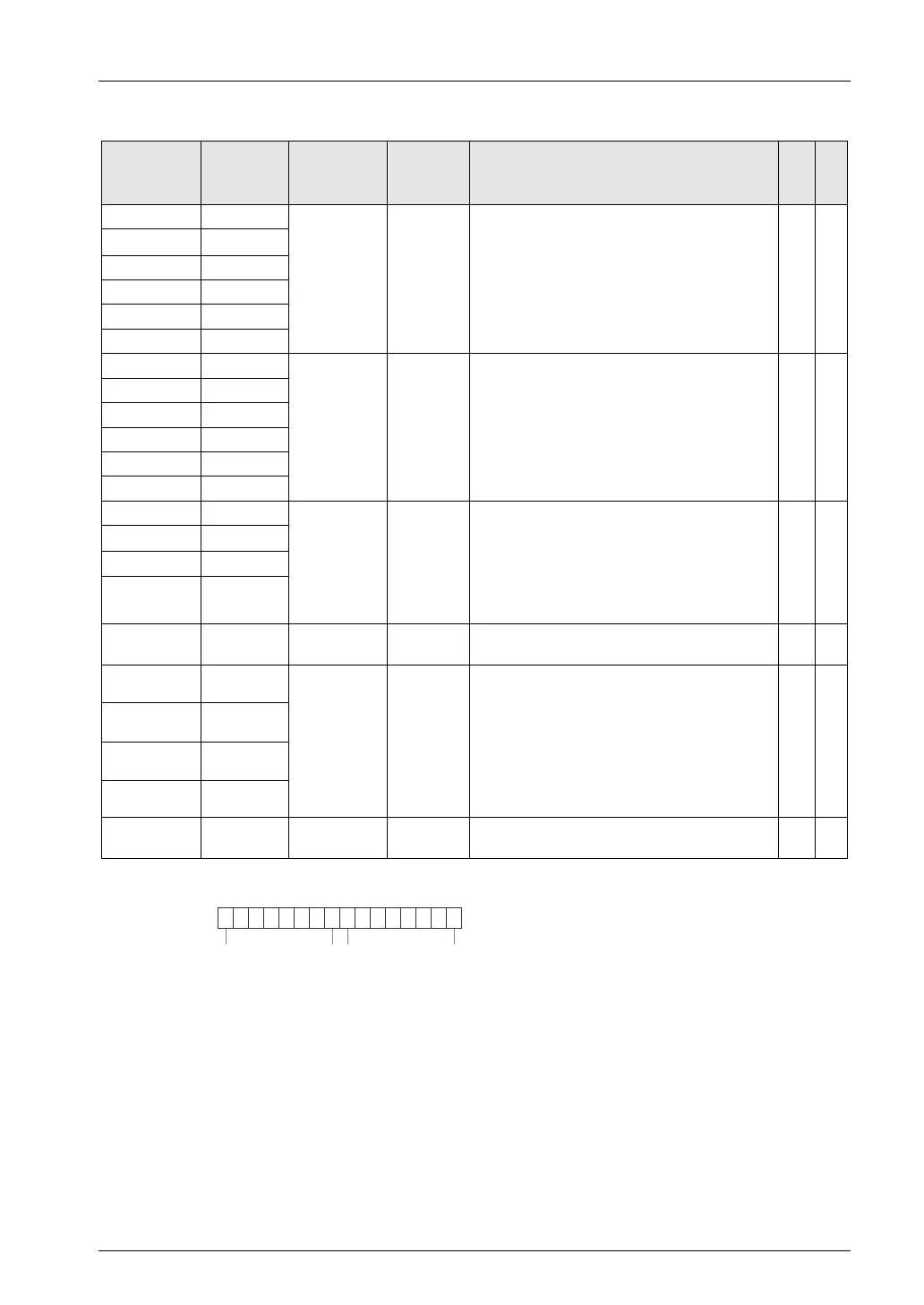
(Note 1): Flags for 16 axes are allocated to each area (1 word).
bit no.
15 08 7
9 1816
● ● ● ● ● ●● ● ● ● ● ●
Axis no.
25 172432
● ● ● ● ● ●● ● ● ● ● ●
41 334048
● ● ● ● ● ●● ● ● ● ● ●
57 495664
● ● ● ● ● ●● ● ● ● ● ●