294 Adding Optional Hardware
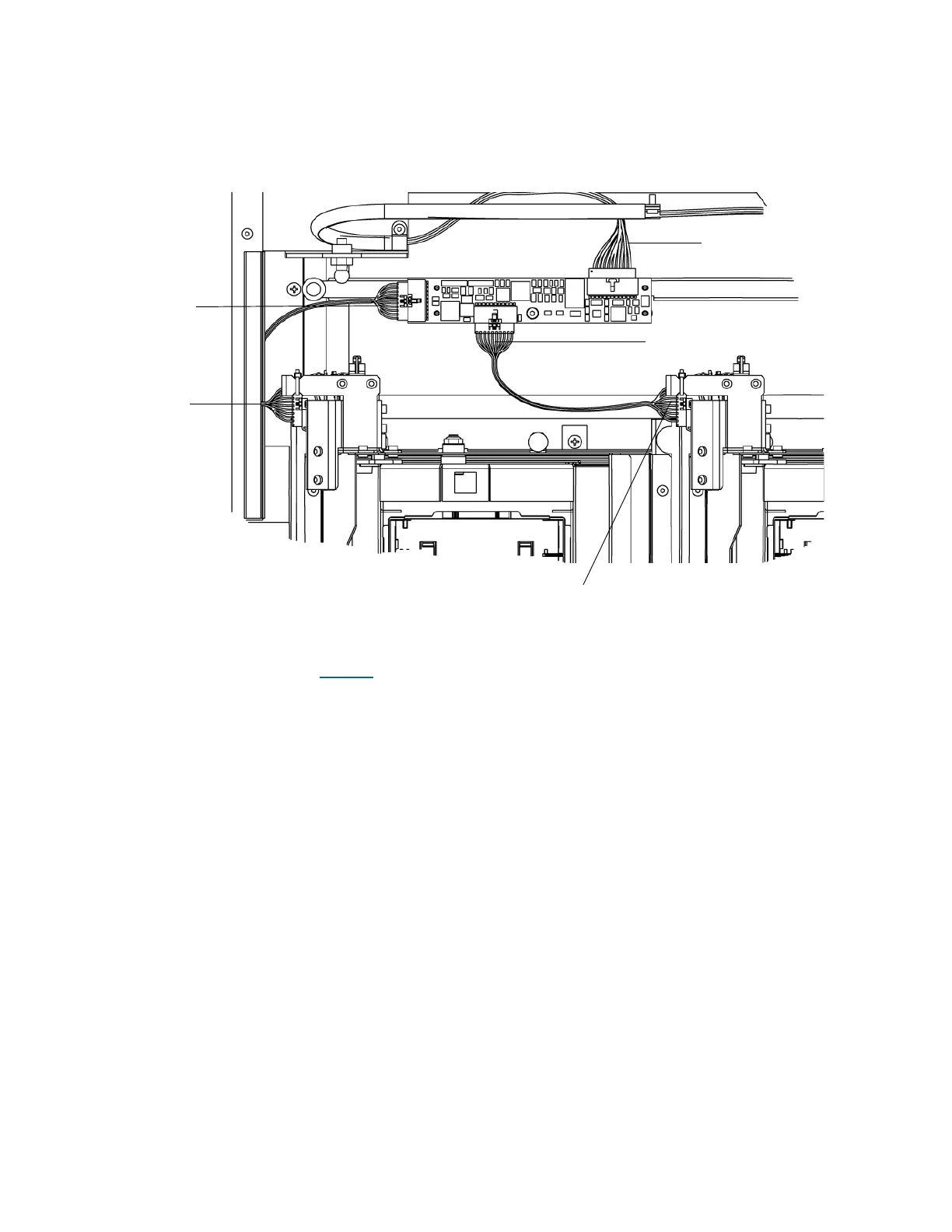
48 On the left I/E station door, attach the 12-pin connector end of the cable to the door lock connector and
the 10-pin cable connector into IEM1 card.
49 On the right I/E station door, connect the 12-pin connector end of the cable to the door lock connector
and the 10-pin connector end to the IEM1 card.
50 On the I/E station closest to the door hinge, tuck the cable behind the door gasket flange.
51 Open and close each I/E station door to ensure proper alignment. If the doors are not opening and
closing properly, return to Step 42
on page 291.
10-pin connector
12-pin connector
12-pin connector
10-pin connector
W6 I/E cable

 Loading...


