Annexes
R&S
®
ZNL/ZNLE
1113User Manual 1178.5966.02 ─ 20
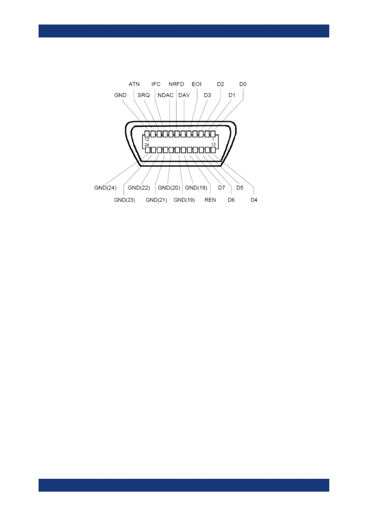
Pin assignment
Bus lines
●
Data bus with 8 lines D0 to D7:
The transmission is bit-parallel and byte-serial in the ASCII/ISO code. D0 is the
least significant bit, D7 the most significant bit.
●
Control bus with five lines:
IFC (Interface Clear): active LOW resets the interfaces of the instruments connec-
ted to the default setting.
ATN (Attention): active LOW signals the transmission of interface messages, inac-
tive HIGH signals the transmission of device messages.
SRQ (Service Request): active LOW enables the connected device to send a ser-
vice request to the controller.
REN (Remote Enable): active LOW permits switchover to remote control.
EOI (End or Identify): has two functions in connection with ATN:
– ATN=HIGH active LOW marks the end of data transmission.
– ATN=LOW active LOW triggers a parallel poll.
●
Handshake bus with three lines:
DAV (Data Valid): active LOW signals a valid data byte on the data bus.
NRFD (Not Ready For Data): active LOW signals that one of the connected devi-
ces is not ready for data transfer.
NDAC (Not Data Accepted): active LOW signals that the instrument connected is
accepting the data on the data bus.
The R&S ZNL/ZNLE provides several functions to communicate via GPIB bus. They
are described in the following sections.
Interfaces and connectors

 Loading...


