Getting Started
R&S
®
ZNL/ZNLE
45User Manual 1178.5966.02 ─ 20
In Spectrum mode or any other application (R&S ZNL only), Port 2 is used as RF
INPUT 50 Ohm.
Port 1 is used to provide an independant CW output signal, if option R&S ZNL/ZNLE-
K14 is installed and active.
4.2.1.9 RF INPUT 50 Ohm
Provides RF input from a connected device under test (DUT) to the R&S ZNL, which is
then analyzed in an RF measurement. Connect the DUT to the "RF Input" on the
R&S ZNL via a cable equipped with an appropriate connector. Do not overload the
input. For maximum allowed values, see the data sheet.
For the R&S ZNLE, the Spectrum mode is not available and hence this connector is
always used as VNA port 2.
See also Chapter 4.1.13, "Considerations for test setup", on page 37.
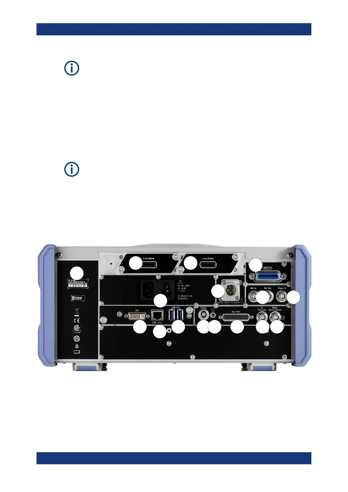
4.2.2 Rear panel view
This figure shows the rear panel view of the R&S ZNL/ZNLE. The individual elements
are described in more detail in the subsequent sections.
21
14 15
4
6
138
3
10
9
11
16
5
7
12
Figure 4-3: Rear panel view R&S
ZNL
1+2 = Removable, rechargeable Li-ion batteries
3 = DC power supply
4 = AC power supply connection and main power switch with fuse
5 = GPIB (IEC 625) interface
6 = Reference clock connectors
7 = Trigger input connector
Instrument tour

 Loading...


