VNA GUI reference
R&S
®
ZNL/ZNLE
531User Manual 1178.5966.02 ─ 20
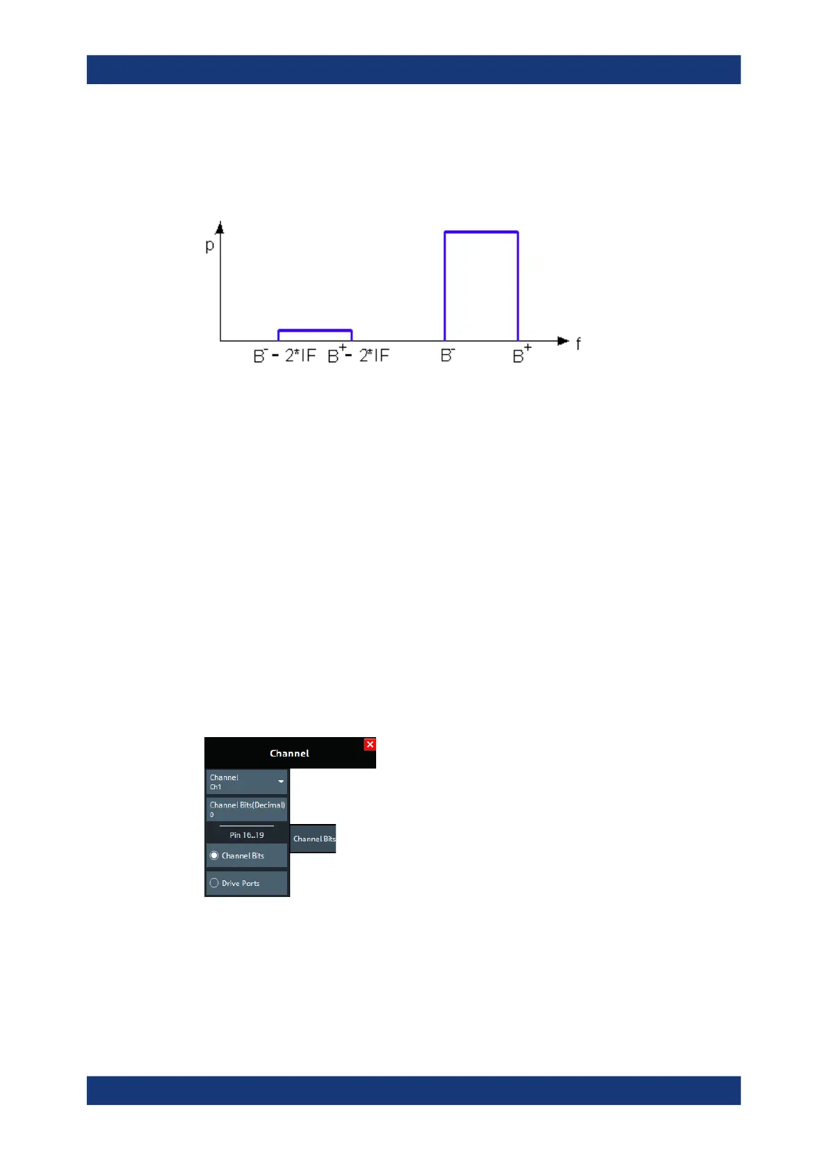
LO > RF implies that LO = RF + IF. The mixer at port 2 converts both the wanted signal
b
2
and the spurious signal b'
2
which is at the frequency RF' = IF + LO, to the same IF
frequency. The response of an ideal, infinitely steep bandpass filter with a pass band
between B
-
and B
+
looks as follows:
For a wide bandpass, the spurious response flattens the filter edges.
The spurious signal can be eliminated by dividing the sweep range into two segments
with different LO settings:
●
In the low-frequency segment ranging up to the center frequency of the bandpass
filter, the frequency of the local oscillator is set to LO < RF. This setting ensures
that the spurious signal b'
2
is not measured at port 2.
●
In the high-frequency segment, starting at the center frequency of the bandpass fil-
ter, the frequency of the local oscillator is set to LO > RF. If the center frequency is
larger than B
+
– 2*IF, then there is no distortion from b'
2
.
Remote command:
[SENSe<Ch>:]FREQuency:SBANd
10.13.3 Channel Bits tab
Sets a channel-dependent 8-bit decimal value (0 ... 255) to control eight independent
output signals at the Aux. Port connector (lines 8 to 11 and 16 to 19).
Setting the channel bits does not change the analyzer state.
Channel softtool

 Loading...


