VNA concepts and features
R&S
®
ZNL/ZNLE
279User Manual 1178.5966.02 ─ 20
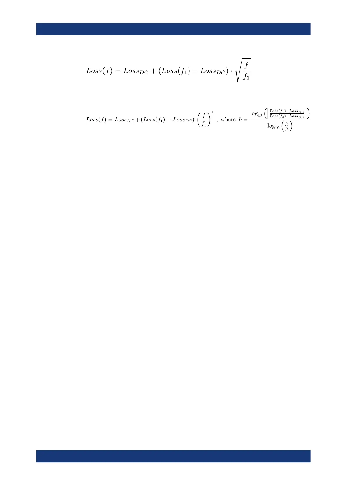
If in addition the loss at a second frequency f
2
is known (or measured), then the loss
can be approximated by:
In practice, the frequency-dependent part ist often dominant, so that Loss
DC
can be set
to zero. Experimentally, the loss value at DC can be determined in a separate mea-
surement at a very low frequency (f --> 0).
9.6.1.3 Auto Length
The "Auto Length" function adds an electrical length offset to the active trace's receive
port, such that the residual delay of the active trace (defined as the negative derivative
of the phase response) is minimized across a configurable frequency range. If "Delay"
is the selected trace format, the entire trace is shifted in vertical direction and centered
on zero. In phase format, the "Auto Length" corrected trace shows the deviation from
linear phase.
Length and delay measurement, related settings
"Auto Length" is suited for length and delay measurements on transmission lines.
1. Connect a (non-dispersive) cable to a single analyzer port no. n and measure the
reflection factor S
nn
.
2. In the [Offset Embed] > "Offset" softtool tab, select "Auto Length".
The delay is displayed in the "Delay" field, the cable length (depending on the
"Velocity Factor") in the "Mech. Length" field.
It is also possible to determine cable lengths using a transmission measurement. Note
that "Auto Length" always provides the single cable length and the delay for propaga-
tion in one direction.
The analyzer provides alternative ways for delay measurements:
1. Measure the reflection factor and select [Format] > "Delay".
This yields the delay for propagation in forward and reverse direction and should
be approx. twice the "Auto Length" result. For transmission measurements, both
results should be approx. equal.
2. Measure the reflection factor and select [Format] > "Phase". Place a marker to the
trace and activate [Trace] > "Trace Statistics" > "Phase/El Length".
Offset parameters and de-/embedding

 Loading...


