VNA GUI reference
R&S
®
ZNL/ZNLE
503User Manual 1178.5966.02 ─ 20
Related information
Refer to the following sections:
●
Chapter 9.5.2.4, "Cal kit Files", on page 260
●
"Kit Standards dialog" on page 500
●
Chapter 9.5.2.1, "Calibration standard types", on page 256
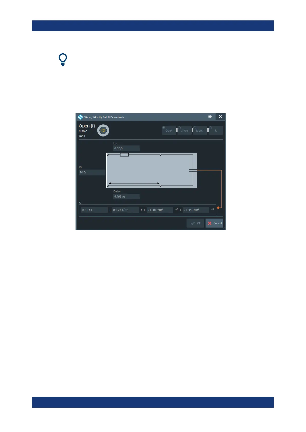
Access: Kit Standards dialog > "View / Modify..."
The diagram in the "View / Modify Cal Kit Standards" dialog depends on the standard
type for which the dialog was opened. Moreover, it is possible to modify the circuit
model using the buttons in the upper right of the dialog.
Offset Parameters
The entries in the upper part of the "View / Modify Cal Kit Standards" dialog specify the
offset parameters for the transmission lines of the selected calibration standard.
The offset parameters depend on whether the circuit model is defined as "Keysight
Model" (see Chapter 10.12.2.1, "Cal Connector Types dialog", on page 496):
●
In a "Keysight Model", a calibration standard is characterized by its "Delay" (in s),
its characteristic impedance "Z0" (in Ω) and its "Offset Loss" (in GΩ/s).
●
Otherwise the standard is characterized by the R&S ZVR-compatible parameters
"Electrical Length" (in m), "Char. Imp." (in Ω) and "Loss" (in dB/sqrt(GHz)). The loss
is zero and not editable as long as the electrical length is zero.
Both parameter sets are closely related. The "Electrical Length" is proportional to the
"Delay"; "Z0" corresponds to the "Char. Imp.". Moreover the analyzer converts a Key-
sight-type "Offset Loss" into a R&S ZVR-type "Loss" and vice versa using the "Rel.
Permittivity εr" for the selected connector type.
See also description of the offset parameters in Chapter 9.5.2.1, "Calibration standard
types", on page 256.
Cal softtool

 Loading...


