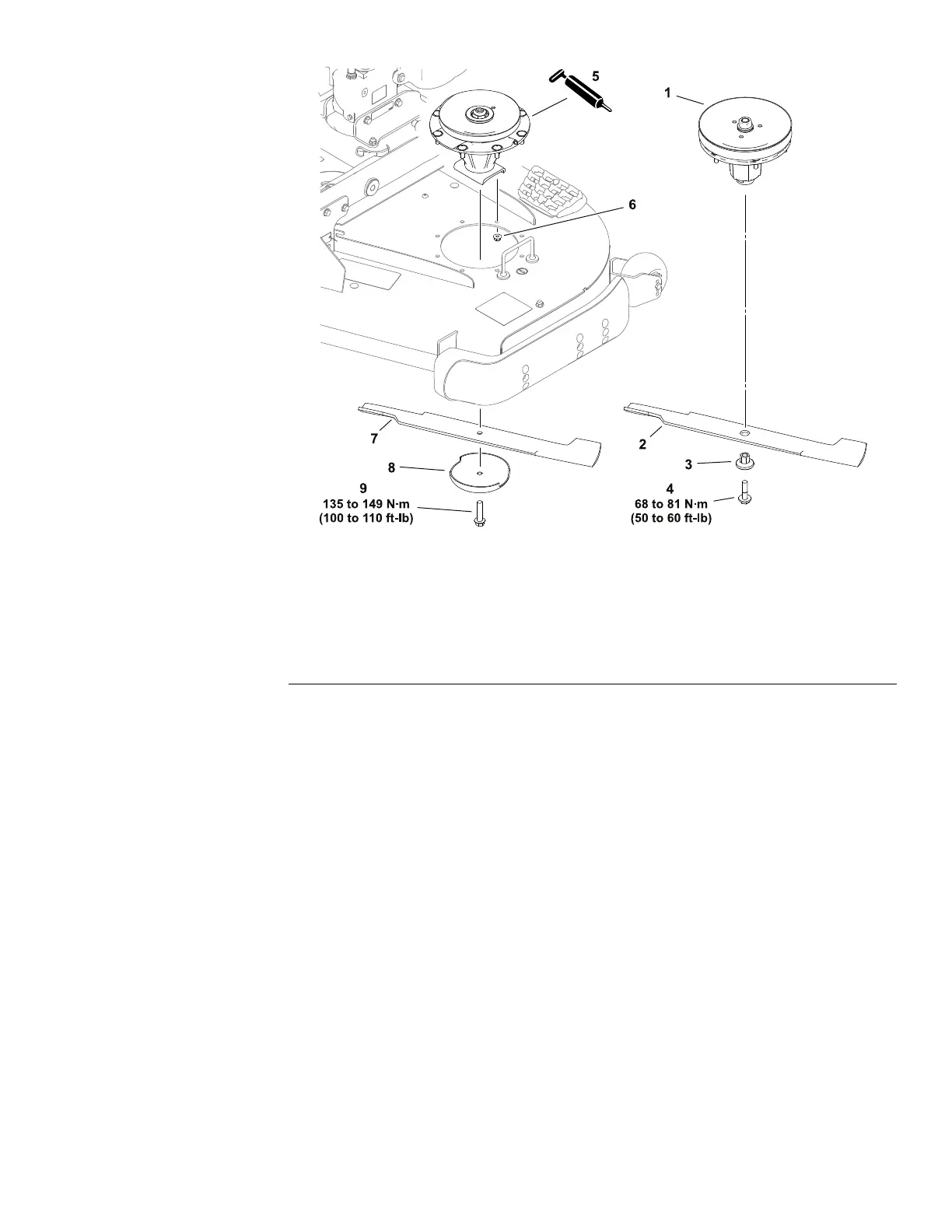
BladeSpindleAssemblies
g315082
Figure133
1.Spindleassembly–Standard6.Flangenut(6or8each)
2.Blade–Standard7.Blade–Groundsmaster
3.Hexbushing–Standard8.Anti-scalpcup–Groundsmaster
4.Bladebolt–Standard9.Bladebolt–Groundsmaster
5.Spindleassembly–Groundsmaster
RemovingtheBladeSpindleAssemblies
RefertoFigure133forthisprocedure.
1.Parkthemachineonalevelsurface,lowerthecuttingunit,engagethe
parkingbrake,setthekeyswitchtotheOFFpositionandremovethekey
fromthekeyswitch.
2.Removethebeltcoversandthedrivebeltfromthecuttingunit;refertothe
cuttingunitOperator’sManual.
3.RotatethecuttingunittotheSERVICEposition;refertothetractionunit
Operator’sManual.
4.Removethebladebolt,hexbushingoranti-scalpcup,andbladefromthe
spindle.
5.Removethefastenersthatsecurethespindleassemblytothedeck,and
removethespindleassemblyfromthedeck.
InstallingtheBladeSpindleAssemblies
RefertoFigure133forthisprocedure.
1.Positionthespindleassemblytothecuttingunitdeck.
A.ForStandardseriescuttingunits,thespindlehousinghasalocating
featurethatmusttintothelocatingholeinthedeck.Thebottomofthe
spindlehousingspacermusttatagainstthedeckonceinstalled.
Groundsmaster
®
3200,3300and3310
Page8–7
CuttingUnits:ServiceandRepairs
19240SLRevA