ENGINE
4-168 Rev. 000 TX525 Service Manual
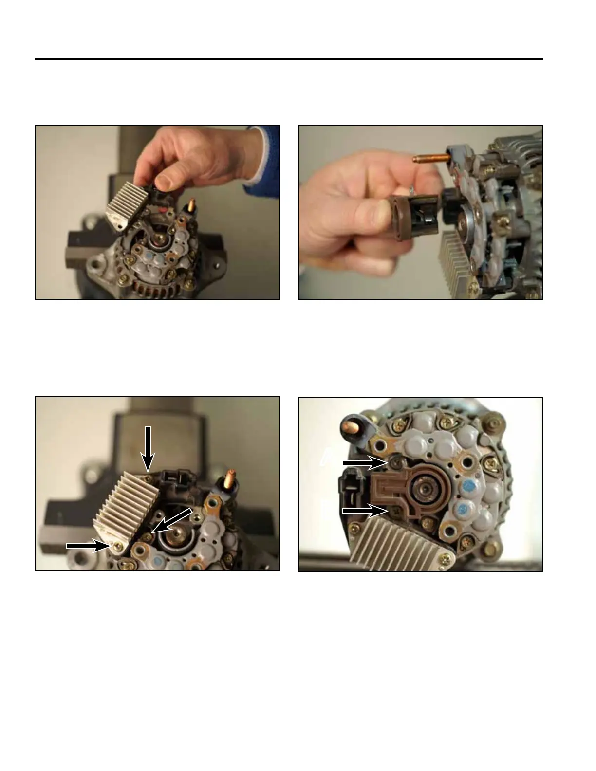
Fig 0715 PICT-8255
16. Positionthebrushholderontothealternatoras-
sembly(Fig.0715).
14. Positiontheregulatorassemblytothealternator
(Fig.0713).
Fig 0713 PICT-8250
15. Install3screwstosecuretheregulatorassemblyto
thealternator(Fig.0714).
Fig 0714 PICT-8253
17. Install2screwssecuringthebrushholdertothe
alternatorassembly(Fig.0716).
Fig 0716 PICT-8178
A. Longerscrew B. Shorterscrew
A
B